AUTOMATIC HIGH BEAM SYSTEM TERMINALS OF ECU

-
CHECK INSTRUMENT PANEL JUNCTION BLOCK ASSEMBLY AND MAIN BODY ECU (MULTIPLEX NETWORK BODY ECU)
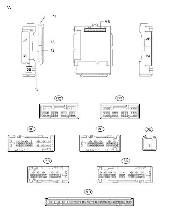
Text in Illustration *A Main Body ECU (Multiplex Network Body ECU) with 2 Connectors - - *1 Main Body ECU (Multiplex Network Body ECU) - - *a 2 Connectors - - 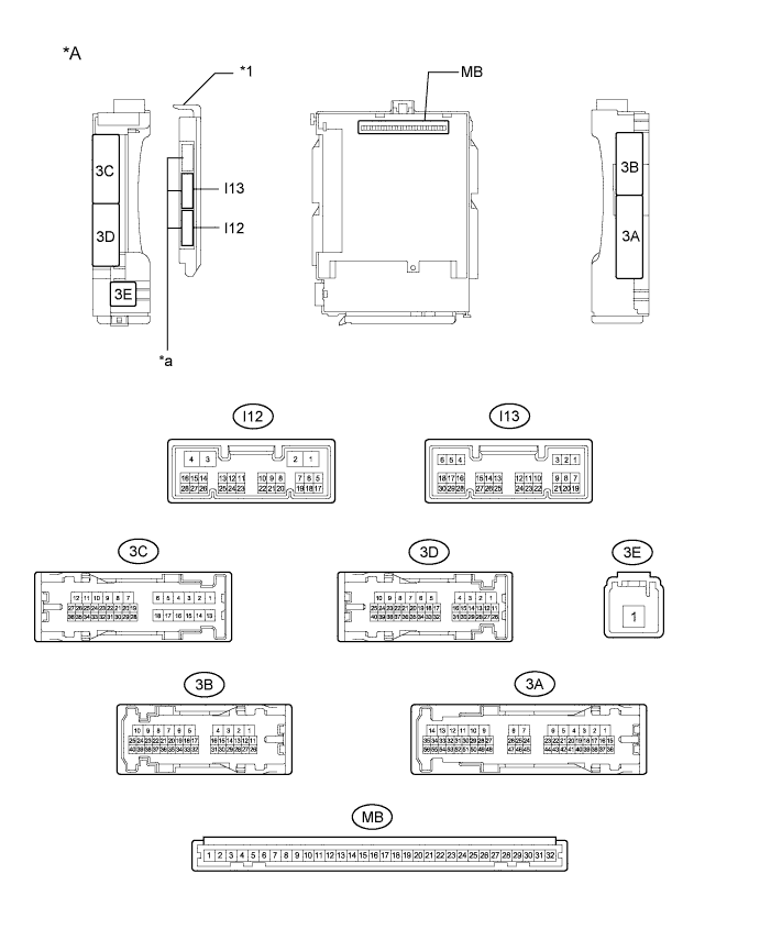
Text in Illustration *A Main Body ECU (Multiplex Network Body ECU) with 3 Connectors - - *1 Main Body ECU (Multiplex Network Body ECU) - - *a 3 Connectors - -
-
Measure the voltage and check for pulses according to the value(s) in the table below.
Terminal No. (Symbol) Wiring Color Terminal Description Condition Specified Condition 3D-39 - Body ground W - Body ground High beam headlight drive output Dimmer switch in high or high flash position Below 1 V Dimmer switch in low position 11 to 14 V I13-5 (HU) - Body ground LG - Body ground Dimmer switch high position signal input Dimmer switch in high position Below 1 V Dimmer switch not in high position Pulse generation I13-20 (CLTB) - I13-22 (CLTE) B - P Automatic light control sensor power supply output Ignition switch off Below 1 V Ignition switch ON, light control switch in AUTO position 11 to 14 V I13-21 (CLTS) - Body ground G - Body ground Automatic light control sensor signal input Ignition switch off Below 1 V Automatic light control system operating Pulse generation
(See waveform 1)
I13-28 (A) - Body ground G - Body ground Light control switch AUTO position signal input Light control switch in AUTO position Below 1 V Light control switch not in AUTO position Pulse generation If the result is not as specified, the main body ECU (multiplex network body ECU) or instrument panel junction block assembly may be malfunctioning.
-
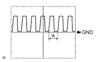
Waveform 1
Item Content Tool setting 5 V/DIV., 5 ms./DIV. Tech Tips
As the ambient light becomes brighter, width (A) becomes narrower.
-
-
-
CHECK LANE DEPARTURE WARNING CAMERA Click here