WIRELESS CHARGING SYSTEM Wireless Charger Illumination Circuit
DESCRIPTION
When the light control switch is turned to the tail or head position, this circuit sends an illumination signal to the upper console panel sub-assembly. Based on this signal, the upper console panel sub-assembly dims the indicator lights (green and amber).
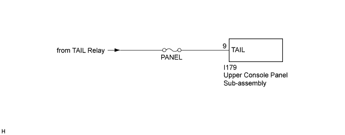
WIRING DIAGRAM
INSPECTION PROCEDURE
Note
Inspect the fuses for circuits related to this system before performing the following inspection procedure.
PROCEDURE
-
CHECK HARNESS AND CONNECTOR (ILLUMINATION SIGNAL)
-
Disconnect the I179 upper console panel sub-assembly connector.
-
Measure the voltage according to the value(s) in the table below.
Standard Voltage Tester Connection Condition Specified Condition I179-9 (TAIL) - Body ground Light control switch in tail or head position 11 to 14 V
NG 
REPAIR OR REPLACE HARNESS OR CONNECTOR
OK 
PROCEED TO NEXT SUSPECTED AREA SHOWN IN PROBLEM SYMPTOMS TABLE Click here
-