WIRELESS CHARGING SYSTEM Status Signal Circuit
DESCRIPTION
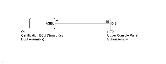
This circuit sends a smart key system status signal from the certification ECU (smart key ECU assembly) to the upper console panel sub-assembly. Based on this signal, the upper console panel sub-assembly suspends or resumes wireless charging.
WIRING DIAGRAM
INSPECTION PROCEDURE
Note
Before replacing the certification ECU (smart key ECU assembly), refer to the Registration ( Click here).
PROCEDURE
-
INSPECT UPPER CONSOLE PANEL SUB-ASSEMBLY
-
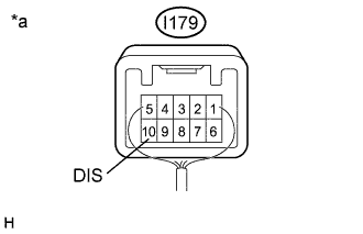
Text in Illustration *a Component with harness connected
(Upper Console Panel Sub-assembly)
Measure the voltage according to the value(s) in the table below.
Standard Voltage Tester Connection Condition Specified Condition I179-10 (DIS) - Body ground For 1500 ms after turning engine switch from off to on (IG)*1 4.4 to 6.5 V Being charged Below 1 V Charging suspended due to smart key system status*2 4.4 to 6.5 V Tech Tips
-
*1: The upper console panel sub-assembly checks the status signal for 1500 ms when the engine switch is turned from off to on (IG). If a status signal voltage of less than 1 V continues for 400 ms or more during the check, the upper console panel sub-assembly judges that the status signal is interrupted, blinks the indicators and stops the operation until the engine switch is turned off then on (IG) again.
-
*2: For the status of the smart key system when charging is stopped temporarily, refer to System Description Click here.
-
NG 
CHECK HARNESS AND CONNECTOR (UPPER CONSOLE PANEL SUB-ASSEMBLY - CERTIFICATION ECU (SMART KEY ECU ASSEMBLY)) Click here
OK 
PROCEED TO NEXT SUSPECTED AREA SHOWN IN PROBLEM SYMPTOMS TABLE Click here
-
-
CHECK HARNESS AND CONNECTOR (UPPER CONSOLE PANEL SUB-ASSEMBLY - CERTIFICATION ECU (SMART KEY ECU ASSEMBLY))
-
Disconnect the I179 upper console panel sub-assembly connector.
-
Disconnect the O1 certification ECU (smart key ECU assembly) connector.
-
Measure the resistance according to the value(s) in the table below.
Standard Resistance Tester Connection Condition Specified Condition I179-10 (DIS) - O1-7 (ASEL) Always Below 1 Ω I179-10 (DIS) - Body ground Always 10 kΩ or higher
NG 
REPAIR OR REPLACE HARNESS OR CONNECTOR
OK
REPLACE CERTIFICATION ECU (SMART KEY ECU ASSEMBLY) Click here
-