WIRELESS CHARGING SYSTEM Main Switch Signal Circuit
DESCRIPTION
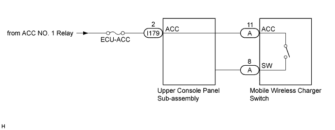
When the mobile wireless charger switch is turned on, this circuit sends an on signal to the upper console panel sub-assembly using the power supplied to the mobile wireless charger switch.
WIRING DIAGRAM
INSPECTION PROCEDURE
Note
Inspect the fuses for circuits related to this system before performing the following inspection procedure.
PROCEDURE
-
INSPECT MOBILE WIRELESS CHARGER SWITCH
-
Remove the mobile wireless charger switch Click here.
-
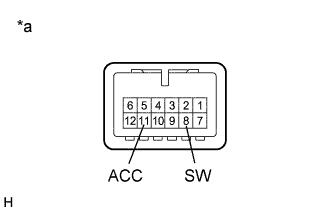
Text in Illustration *a Component without harness connected
(Mobile Wireless Charger Switch)
Measure the resistance according to the value(s) in the table below.
Standard Resistance Tester Connection Condition Specified Condition 11 (ACC) - 8 (SW) Mobile wireless charger switch is on (not protruding) Below 1 Ω Mobile wireless charger switch is off (protruding) 10 kΩ or higher
NG 
REPLACE MOBILE WIRELESS CHARGER SWITCH Click here
OK 
PROCEED TO NEXT SUSPECTED AREA SHOWN IN PROBLEM SYMPTOMS TABLE Click here
-