WIRELESS CHARGING SYSTEM Main Switch Power Source Circuit
DESCRIPTION
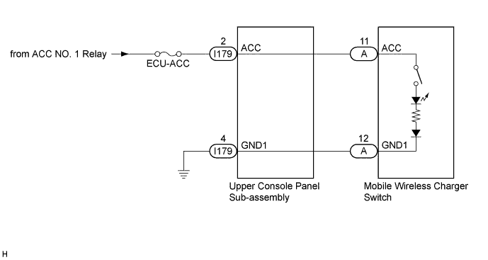
This circuit supplies power to the mobile wireless charger switch and illuminates the switch indicator light when the mobile wireless charger switch is turned on.
WIRING DIAGRAM
INSPECTION PROCEDURE
Note
Inspect the fuses for circuits related to this system before performing the following inspection procedure.
PROCEDURE
-
CHECK HARNESS AND CONNECTOR (UPPER CONSOLE PANEL SUB-ASSEMBLY POWER SOURCE)
-
Disconnect the I179 upper console panel sub-assembly connector.
-
Measure the resistance according to the value(s) in the table below.
Standard Resistance Tester Connection Condition Specified Condition I179-4 (GND1) - Body ground Always Below 1 Ω -
Measure the voltage according to the value(s) in the table below.
Standard Voltage Tester Connection Condition Specified Condition I179-2 (ACC) - I179-4 (GND1) Engine switch on (ACC) 11 to 14 V
NG 
REPAIR OR REPLACE HARNESS OR CONNECTOR
OK 
-
-
INSPECT UPPER CONSOLE PANEL SUB-ASSEMBLY
-
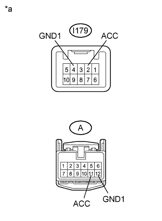
Text in Illustration *a Component without harness connected
(Upper Console Panel Sub-assembly)
Disconnect the I179 and A upper console panel sub-assembly connectors.
-
Measure the resistance according to the value(s) in the table below.
Standard Resistance Tester Connection Condition Specified Condition I179-2 (ACC) - A-11 (ACC) Always Below 1 Ω I179-4 (GND1) - A-12 (GND1) Always Below 1 Ω
NG
REPLACE UPPER CONSOLE PANEL SUB-ASSEMBLY Click here
OK 
PROCEED TO NEXT SUSPECTED AREA SHOWN IN PROBLEM SYMPTOMS TABLE Click here
-