CONDENSER REMOVAL

-
PRECAUTION
Note
After turning the ignition switch off, waiting time may be required before disconnecting the cable from the negative (-) battery terminal. Therefore, make sure to read the disconnecting the cable from the negative (-) battery terminal notices before proceeding with work Click here.
-
RECOVER REFRIGERANT FROM AIR CONDITIONING SYSTEM
-
Turn the A/C switch on.
-
Operate the air conditioning with a set temperature of 25°C (77°F) and the blower at low for 10 minutes to circulate the refrigerant. This causes most of the compressor oil from the various components of the air conditioning system to collect in the air conditioning compressor.
-
Turn the ignition switch off.
-
Recover the refrigerant from the air conditioning system using a refrigerant recovery unit.
-
-
DISCONNECT CABLE FROM NEGATIVE BATTERY TERMINAL
Note
When disconnecting the cable, some systems need to be initialized after the cable is reconnected Click here.
-
REMOVE FRONT BUMPER ASSEMBLY
-
REMOVE MILLIMETER WAVE RADAR SENSOR ASSEMBLY (w/ Dynamic Radar Cruise Control System)
-
REMOVE BATTERY (for 2GR-FE)
-
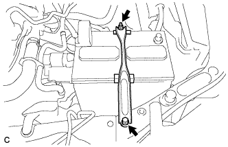
Loosen the nut, and separate the positive (+) battery terminal.
-
Loosen the nut and remove the bolt and battery clamp.
-
Remove the battery and battery tray.
-
-
REMOVE INLET AIR CLEANER ASSEMBLY (for 2AR-FE)
-
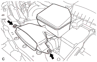
Remove the 2 bolts and inlet air cleaner assembly.
-
-
REMOVE INLET NO. 2 AIR CLEANER (for 2GR-FE)
-
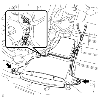
Disconnect the 2 wire harness clamps and vacuum hose clamp.
-
Remove the 2 bolts and inlet No. 2 air cleaner from the air cleaner case sub-assembly.
-
-
REMOVE INLET NO. 1 AIR CLEANER (for 2GR-FE)
-
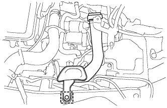
Disengage the pin and remove the inlet No. 1 air cleaner.
-
-
REMOVE HOOD LOCK ASSEMBLY
-
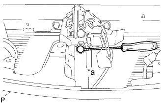
Text in Illustration *a Protective Tape Using a screwdriver, remove the hood lock nut cap.
Tech Tips
Tape the screwdriver tip before use.
-
w/ Engine Hood Courtesy Switch:
-
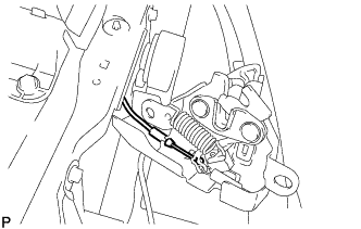
Disconnect the connector.
-
-
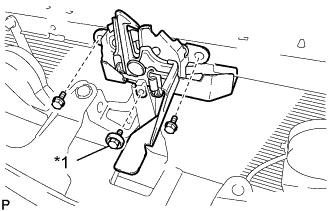
Text in Illustration *1 Hood Lock Bolt Remove the 2 bolts and hood lock bolt.
-
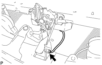
Disconnect the hood lock control cable assembly and remove the hood lock assembly.
-
-
REMOVE UPPER RADIATOR SUPPORT (for 2AR-FE)
-
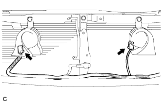
Disconnect the 2 connectors.
-
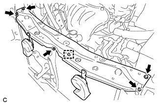
Disconnect the hood lock control cable clamp and remove the 5 bolts and upper radiator support.
-
Remove the 2 radiator support cushions.
-
-
REMOVE UPPER RADIATOR SUPPORT (for 2GR-FE)
-
Disconnect the 2 connectors.
-
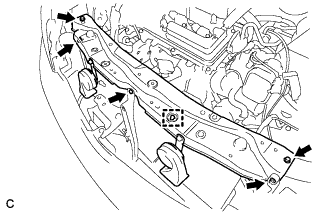
Disconnect the hood lock control cable clamp and remove the 5 bolts and upper radiator support.
-
Remove the 2 radiator support cushions from the radiator assembly.
-
-
REMOVE RADIATOR SIDE DEFLECTOR LH
-
Disengage the 3 claws and guide, and remove the radiator side deflector LH.
-
-
REMOVE RADIATOR SIDE DEFLECTOR RH
-
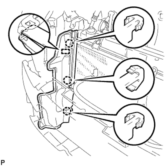
Disengage the 3 claws and guide, and remove the radiator side deflector RH.
-
-
DISCONNECT NO. 1 COOLER REFRIGERANT DISCHARGE HOSE
-
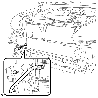
Remove the bolt and disconnect the No. 1 cooler refrigerant discharge hose from the cooler condenser assembly.
-
Remove the O-ring from the No. 1 cooler refrigerant discharge hose.
Note
Seal the openings of the disconnected parts using vinyl tape to prevent entry of moisture and foreign matter.
-
-
DISCONNECT AIR CONDITIONING TUBE AND ACCESSORY ASSEMBLY
-
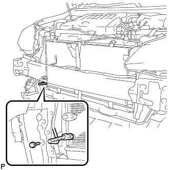
Remove the bolt and disconnect the air conditioning tube and accessory assembly from the cooler condenser assembly.
-
Remove the O-ring from the air conditioning tube and accessory assembly.
Note
Seal the openings of the disconnected parts using vinyl tape to prevent entry of moisture and foreign matter.
-
-
REMOVE COOLER CONDENSER ASSEMBLY
-
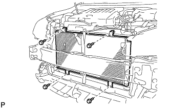
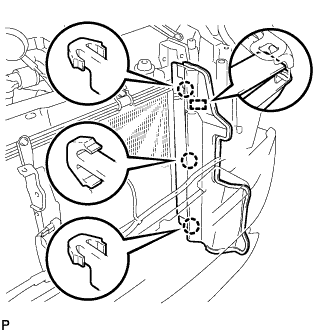
Remove the 4 bolts.
-
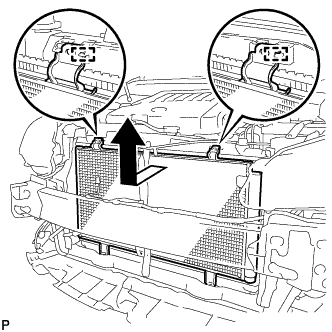
Disengage the 2 guides and remove the cooler condenser assembly as shown in the illustration.
-