SEAT BELT WARNING SYSTEM TERMINALS OF ECU

-
CHECK COMBINATION METER ASSEMBLY
-
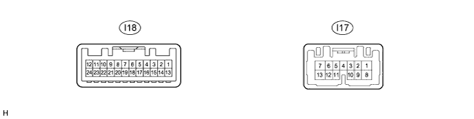
Disconnect the I18 combination meter assembly connector.
-
Measure the resistance according to the value(s) in the table below.
Tech Tips
Measure the values on the wire harness side with the connector disconnected.
Tester Connection Wiring Color Terminal Description Condition Specified Condition I18-7 (ES)*1 - Body ground BR - Body ground Ground Always Below 1 Ω I18-20 (ES)*2 - Body ground BR - Body ground Ground Always Below 1 Ω
-
*1: w/o Multi-information Display
-
*2: w/ Multi-information Display
If the result is not as specified, there may be a malfunction in the wire harness.
-
-
Reconnect the I18 combination meter assembly connector.
-
Measure the voltage according to the value(s) in the table below.
Tester Connection Wiring Color Terminal Description Condition Specified Condition I18-1 (B) - Body ground W - Body ground Battery power supply Always 11 to 14 V I18-13 (IG+) - Body ground L - Body ground Ignition power supply
(IG signal)
Ignition switch off Below 1 V I18-13 (IG+) - Body ground L - Body ground Ignition power supply
(IG signal)
Ignition switch ON 11 to 14 V If the result is not as specified, the combination meter assembly may have a malfunction.
-
-
CHECK AIRBAG SENSOR ASSEMBLY
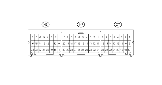
Terminal No. Terminal Symbol Destination N5-10 LBE+ Front seat inner belt assembly LH N5-18 LBE- Front seat inner belt assembly LH O7-16 FSR+ Occupant detection ECU O7-24 FSR- Occupant detection ECU -
CHECK OCCUPANT DETECTION ECU
-
Measure the voltage according to the value(s) in the table below.
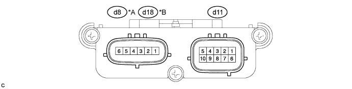
Text in Illustration *A for TMMK Made *B for SIA Made Tester Connection Wiring Color Terminal Description Condition Specification d11-1 (+B) - d11-3 (GND) W*1 - W-B
R*2 - W-B
Battery Always 11 to 14 V d11-2 (DIA) - d11-3 (GND) GR - W-B Diagnosis (DLC3) Ignition switch ON, Techstream not connected to DLC3 Below 1 V d11-3 (GND) - Body ground W-B - Body ground Ground Always Below 1 V d11-4 (FSR-) - d11-3 (GND) Y - W-B*1
B - W-B*2
Airbag sensor assembly communication line Always Below 1 V d11-5 (BGND) - d11-3 (GND) P - W-B Front passenger buckle switch ground line Always Below 1 V d11-6 (IG2) - d11-3 (GND) B*1 - W-B
SB*2 - W-B
Power source Ignition switch ON 11 to 14 V d11-7 (FSR+) - d11-4 (FSR-) L - Y*1
W - B*2
Airbag sensor assembly communication line Ignition switch ON Pulse generation d11-8 (BSW) - d11-5 (BGND) G - P Front passenger buckle switch line Always Pulse generation d8-1 (SVC1) - d8-5 (SGD1)*1
d18-1 (SVC1) - d18-5 (SGD1)*2
R - G Front occupant classification sensor power supply line Ignition switch ON 4.9 to 5.1 V d8-2 (SVC3) - d8-6 (SGD3)*1
d18-2 (SVC3) - d18-6 (SGD3)*2
GR - W Rear occupant classification sensor power supply line Ignition switch ON 4.9 to 5.1 V d8-3 (SIG1) - d8-5 (SGD1)*1
d18-3 (SIG1) - d18-5 (SGD1)*2
P - G Front occupant classification sensor signal line Ignition switch ON Pulse generation d8-4 (SIG3) - d8-6 (SGD3)*1
d18-4 (SIG3) - d18-6 (SGD3)*2
Y - W*1
SB - W*2
Rear occupant classification sensor signal line Ignition switch ON Pulse generation
-
*1: for TMMK Made
-
*2: for SIA Made
If the result is not as specified, the occupant detection ECU may have a malfunction.
-
-