THEFT DETERRENT SYSTEM TERMINALS OF ECU

-
CHECK MAIN BODY ECU (MULTIPLEX NETWORK BODY ECU) AND INSTRUMENT PANEL JUNCTION BLOCK ASSEMBLY
-
Disconnect the main body ECU (multiplex network body ECU) connectors.
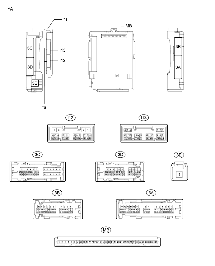
Text in Illustration *A Main Body ECU (Multiplex Network Body ECU) with 2 connectors - - *a 2 Connectors - - 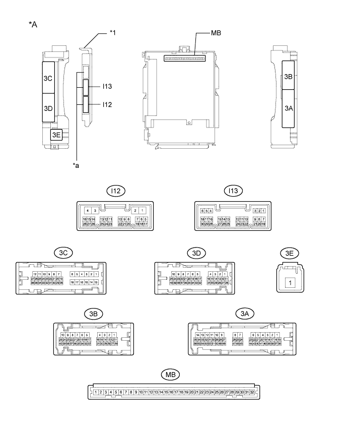
Text in Illustration *A Main Body ECU (Multiplex Network Body ECU) with 3 connectors - - *a 3 Connectors - - -
Measure the resistance and voltage according to the value(s) in the table below.
Tech Tips
Measure the values on the wire harness side with the connector disconnected.
Tester Connection Wiring Color Terminal Description Condition Specified Condition MB-30 (BECU) - Body ground - Battery power supply Always 11 to 14 V MB-31 (ALTB) - Body ground - Battery power supply Always 11 to 14 V MB-32 (IG) - Body ground - Ignition power supply (IG signal) Ignition switch ON → OFF 11 to 14 V → Below 1 V MB-29 (ACC) - Body ground - Ignition power supply (ACC signal) Ignition switch ACC → OFF 11 to 14 V → Below 1 V MB-11 (GND1) - Body ground - Ground Always Below 1 Ω I12-3 (GND2) - Body ground W-B - Body ground Ground Always Below 1 Ω MB-2 (FLCY) - Body ground - Front door courtesy light switch LH input Front door LH closed (OFF) → open (ON) 10 kΩ or higher → Below 1 Ω I13-19 (FRCY) - Body ground SB - Body ground Front door courtesy light switch RH input Front door RH closed (OFF) → open (ON) 10 kΩ or higher → Below 1 Ω I13-1 (LCTY) - Body ground P - Body ground Rear door courtesy light switch LH input Rear door LH closed (OFF) → open (ON) 10 kΩ or higher → Below 1 Ω I13-6 (RCTY) - Body ground B - Body ground Rear door courtesy light switch RH input Rear door RH closed (OFF) → open (ON) 10 kΩ or higher → Below 1 Ω MB-4 (LGCY) - Body ground - Luggage compartment door courtesy light switch input Luggage compartment door closed (OFF) → open (ON) 10 kΩ or higher → Below 1 Ω MB-20 (HCTY) - Body ground - Engine hood courtesy switch input Engine hood open (OFF) → closed (ON) 10 kΩ or higher → Below 1 Ω I13-17 (KSW) - Body ground*1 G - Body ground Unlock warning switch input Key is not in the key cylinder (OFF) → Key is in the key cylinder (ON) 10 kΩ or higher → Below 1 Ω MB-14 (TRLY) - Body ground*2 - Supply battery to taillight relay drive Always 11 to 14 V
-
*1: w/o Smart Key System
-
*2: w/o Side Turn Signal Light
If the result is not as specified, there may be a malfunction in the wire harness.
-
-
Reconnect the main body ECU (multiplex network body ECU) connectors.
-
Measure the voltage and resistance according to the value(s) in the table below.
Tester Connection Wiring Color Terminal Description Condition Specified Condition I13-7 (LSFL) - Body ground V - Body ground Front door LH unlock detection switch input Front door LH unlocked Below 1 V I13-7 (LSFL) - Body ground V - Body ground Front door LH unlock detection switch input Front door LH locked Pulse generation I13-18 (LSFR) - Body ground W - Body ground Front door RH unlock detection switch input Front door RH unlocked Below 1 V I13-18 (LSFR) - Body ground W - Body ground Front door RH unlock detection switch input Front door RH locked Pulse generation 3C-17 (LSR) - Body ground LG - Body ground Rear door LH unlock detection switch input Rear door LH or RH unlocked Below 1 V 3C-17 (LSR) - Body ground LG - Body ground Rear door LH unlock detection switch input Rear door LH and RH locked Pulse generation 3A-53 (LSR) - Body ground Y - Body ground Rear door RH unlock detection switch input Rear door RH or LH unlocked Below 1 V 3A-53 (LSR) - Body ground Y - Body ground Rear door RH unlock detection switch input Rear door RH and LH locked Pulse generation I12-22 (IND) - Body ground*4 L - Body ground Security indicator illumination Security indicator light illuminates
(It illuminates only for 57*1 or 27.5*2 sec. in alarm sounding state.)
3 to 10 V 3D-14 (SH) - Body ground R - Body ground Security horn drive Security horn sounding
(Theft deterrent system is in alarm sounding state)
Pulse generation
(Below 1 V ← → 11 to 14 V)
3D-15 (HORN) - Body ground SB - Body ground Vehicle horn drive Vehicle horns sounding
(Theft deterrent system is in alarm sounding state)
Pulse generation
(Below 1 V ← → 11 to 14 V)
3D-12 (HRLY) - Body ground*1 P - Body ground Headlight relay driver output Headlight blinks
(Theft deterrent system is in alarm sounding state)
Pulse generation
(Below 1 V ← → 11 to 14 V)
3B-35 (ILE) - Body ground*1 LG - Body ground Interior light driver output Interior light illuminates
(Theft deterrent system is in alarm sounding state)
11 to 14 V 3B-28 (GBS) - Body ground*3 L - Body ground Glass breakage sensor ECU communication Armed state → alarm sounds (glass breakage sensor detection) Below 1 V → pulse generation
-
*1: w/o Side Turn Signal Light
-
*2: w/ Side Turn Signal Light
-
*3: w/ Glass Breakage Sensor
-
*4: w/o Smart Key System
If the result is not as specified, the main body ECU (multiplex network body ECU) may have a malfunction.
-
-
-
CHECK GLASS BREAKAGE SENSOR ECU (w/ Glass Breakage Sensor)
-
Disconnect the k1 glass breakage sensor ECU connector.

-
Measure the resistance and voltage according to the value(s) in the table below.
Tech Tips
Measure the values on the wire harness side with the connector disconnected.
Tester Connection Wiring Color Terminal Description Condition Specified Condition k1-2 (+B) - Body ground W - Body ground Battery power supply Always 11 to 14 V k1-6 (GND) - Body ground W-B - Body ground Ground Always Below 1 Ω If the result is not as specified, there may be a malfunction in the wire harness.
-