ENGINE IMMOBILISER SYSTEM (w/ Smart Key System), Diagnostic DTC:B279A

| DTC Code | DTC Name |
|---|---|
| B279A | Theft Deterrent System Communication Line High Fixation |
DESCRIPTION
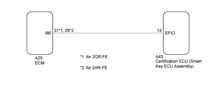
When the communication line (IMI - EFIO) between the ECM and certification ECU (smart key ECU assembly) is stuck high, the ECM stores this DTC.
| DTC Code | DTC Detection Condition | Trouble Area | DTC Output Confirmation Operation |
|---|---|---|---|
| B279A | The communication line (IMI - EFIO) between the ECM and certification ECU (smart key ECU assembly) is stuck high (1 trip detection logic*). |
|
Turn the engine switch on (IG) and wait 6 seconds. |
-
*: Only output while a malfunction is present.
| Vehicle Condition when Malfunction Detected | Fail-safe Operation when Malfunction Detected |
|---|---|
| Engine cannot be started (initial ignition occurs and engine cranks, then ignition stops) | Engine cannot be started |
| DTC Code | Data List and Active Test |
|---|---|
| B279A | - |
WIRING DIAGRAM
INSPECTION PROCEDURE
Note
-
When replacing the certification ECU (smart key ECU assembly), refer to Registration Click here.
-
After performing repairs, perform the operation that fulfills the DTC output confirmation operation, and then confirm that no DTCs are output again.
Tech Tips
When DTC B279A and the certification ECU (smart key ECU assembly) DTC are output simultaneously, first perform troubleshooting for the certification ECU (smart key ECU assembly) DTC.
PROCEDURE
-
CLEAR DTC
-
Clear the DTCs Click here.
NEXT 
-
-
CHECK FOR DTC
-
Turn the engine switch on (IG) and wait 10 seconds.
-
Check for DTCs Click here.
Result Result Proceed to DTC B279A is output A DTC B279A and other DTCs are output B Tech Tips
If DTCs other than DTC B279A are output, troubleshoot those DTCs first.
B 
GO TO DIAGNOSTIC TROUBLE CODE CHART Click here
A
-
-
CHECK CONNECTION OF CONNECTOR
-
Turn the engine switch off.
-
Check that the connectors are properly connected to the ECM and certification ECU (smart key ECU assembly).
OK Connectors are properly connected.
NG
CONNECT CONNECTORS PROPERLY
OK
-
-
CHECK WHETHER ENGINE STARTS
-
Using an electrical key transmitter sub-assembly which is registered to the vehicle, turn the engine switch on (IG).
-
Check that the engine starts 5 seconds after the engine switch was turned on (IG).
OK Engine starts normally. Result Result Proceed to NG A OK B
B
USE SIMULATION METHOD TO CHECK Click here
A
-
-
CHECK HARNESS AND CONNECTOR (CERTIFICATION ECU (SMART KEY ECU ASSEMBLY) - ECM)
-
Disconnect the A43 certification ECU (smart key ECU assembly) connector.
-
Disconnect the A25 ECM connector.
-
Measure the resistance according to the value(s) in the table below.
Standard Resistance for 2GR-FE Tester Connection Condition Specified Condition A43-13 (EFIO) - A25-31 (IMI) Always Below 1 Ω A43-13 (EFIO) or A25-31 (IMI) - Body ground Always 10 kΩ or higher for 2AR-FE Tester Connection Condition Specified Condition A43-13 (EFIO) - A25-28 (IMI) Always Below 1 Ω A43-13 (EFIO) or A25-28 (IMI) - Body ground Always 10 kΩ or higher
NG
REPAIR OR REPLACE HARNESS OR CONNECTOR
OK
-
-
REPLACE CERTIFICATION ECU (SMART KEY ECU ASSEMBLY)
-
Replace the certification ECU (smart key ECU assembly) with a new one Click here.
NEXT
-
-
REGISTER ECU COMMUNICATION ID
-
Register the ECU communication ID Click here.
NEXT
-
-
CLEAR DTC
-
Clear the DTCs Click here.
NEXT
-
-
CHECK FOR DTC
-
Perform "DTC Output Confirmation Operation" procedure.
-
Check for DTCs Click here.
OK DTC B279A is not output. Result Result Proceed to OK A NG (for 2GR-FE) B NG (for 2AR-FE) C
B
REPLACE ECM Click here
C
REPLACE ECM Click here
A 
END (CERTIFICATION ECU (SMART KEY ECU ASSEMBLY) WAS DEFECTIVE)
-