ENGINE IMMOBILISER SYSTEM (w/ Smart Key System), Diagnostic DTC:B278A

| DTC Code | DTC Name |
|---|---|
| B278A | Short to GND in Immobiliser System Power Source Circuit |
DESCRIPTION
When there is a short to GND in the power supply for the transponder key amplifier of the engine switch, the certification ECU (smart key ECU assembly) stores this DTC.
| DTC Code | DTC Detection Condition | Trouble Area | DTC Output Confirmation Operation |
|---|---|---|---|
| B278A | A short to GND in the power supply of the transponder key amplifier of the engine switch (VC5 - VC5) (1 trip detection logic*). |
|
With the shift lever in P, the key held near the engine switch and an engine start operation is performed by pressing and holding the engine switch when the key battery is depleted. |
-
*: Only output while a malfunction is present.
| Vehicle Condition when Malfunction Detected | Fail-safe Operation when Malfunction Detected |
|---|---|
| Engine cannot be started when key battery is depleted by holding key near engine switch and pressing and holding engine switch with shift lever in P | - |
| DTC Code | Data List and Active Test |
|---|---|
| B278A | - |
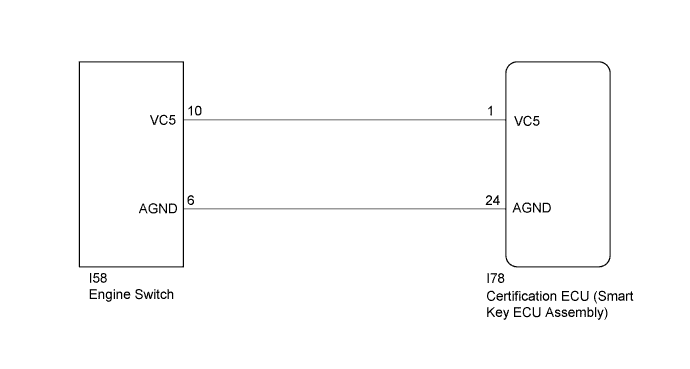
WIRING DIAGRAM
INSPECTION PROCEDURE
Note
-
Before replacing the certification ECU (smart key ECU assembly), refer to Registration Click here.
-
After performing repairs, perform the operation that fulfills the DTC output confirmation operation, and then confirm that no DTCs are output again.
PROCEDURE
-
CHECK CERTIFICATION ECU (SMART KEY ECU ASSEMBLY)
-
Using an oscilloscope, check the waveform.
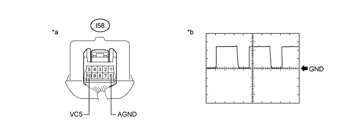
Text in Illustration *a Component with harness connected
(Engine Switch)
*b Waveform Tech Tips
Perform this inspection on the engine switch side.
Measurement Condition Tester Connection Condition Tool Setting Specified Condition I58-10 (VC5) - I58-6 (AGND) Engine switch off, key not in cabin, within 30 seconds after engine switch pressed 2 V/DIV., 200 ms./DIV. Pulse generation
(See waveform)
OK The waveform is similar to that shown in the illustration. Result Result Proceed to NG A OK (for 2GR-FE) B OK (for 2AR-FE) C
B 
REPLACE ENGINE SWITCH Click here
C
REPLACE ENGINE SWITCH Click here
A 
-
-
CHECK HARNESS AND CONNECTOR (CERTIFICATION ECU (SMART KEY ECU ASSEMBLY) - ENGINE SWITCH)
-
Disconnect the I78 certification ECU (smart key ECU assembly) connector.
-
Disconnect the I58 engine switch connector.
-
Measure the resistance according to the value(s) in the table below.
Standard Resistance Tester Connection Condition Specified Condition I78-1 (VC5) - I58-10 (VC5) Always Below 1 Ω I78-24 (AGND) - I58-6 (AGND) Always Below 1 Ω I78-1 (VC5) or I58-10 (VC5) - Body ground Always 10 kΩ or higher I78-24 (AGND) or I58-6 (AGND) - Body ground Always 10 kΩ or higher
NG
REPAIR OR REPLACE HARNESS OR CONNECTOR
OK
-
-
CHECK CERTIFICATION ECU (SMART KEY ECU ASSEMBLY)
-
Reconnect the I78 certification ECU (smart key ECU assembly) connector.
-
Reconnect the I58 engine switch connector.
-
Measure the voltage according to the value(s) in the table below.
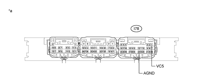
Text in Illustration *a Component with harness connected
(Certification ECU (Smart Key ECU Assembly))
- - Standard Voltage Tester Connection Condition Specified Condition I78-1 (VC5) - I78-24 (AGND) Engine switch off, brake pedal not depressed, 30 seconds or more elapsed after driver door opened and then closed Below 1 V Result Result Proceed to OK (for 2GR-FE) A OK (for 2AR-FE) B NG C
B
REPLACE ENGINE SWITCH Click here
C
REPLACE CERTIFICATION ECU (SMART KEY ECU ASSEMBLY) Click here
A 
REPLACE ENGINE SWITCH Click here
-