WIRELESS DOOR LOCK CONTROL SYSTEM (w/ Smart Key System) TERMINALS OF ECU

-
CHECK INSTRUMENT PANEL JUNCTION BLOCK ASSEMBLY AND MAIN BODY ECU (MULTIPLEX NETWORK BODY ECU)
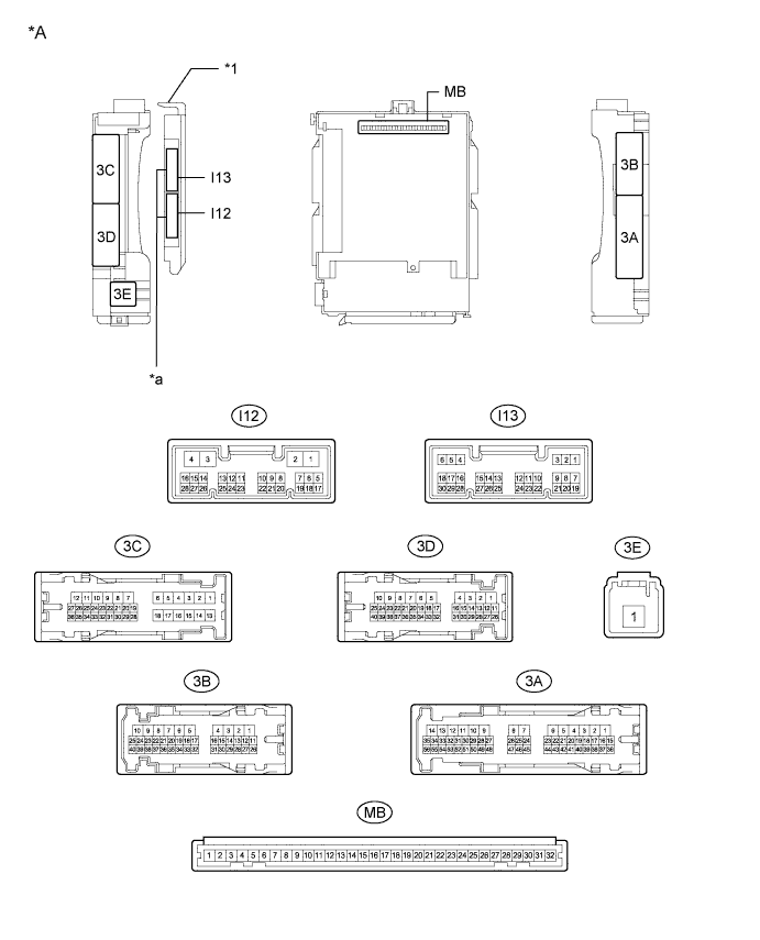
Text in Illustration *A Main Body ECU (Multiplex Network Body ECU) with 2 connectors - - *1 Main Body ECU (Multiplex Network Body ECU) - - *a 2 connectors - - 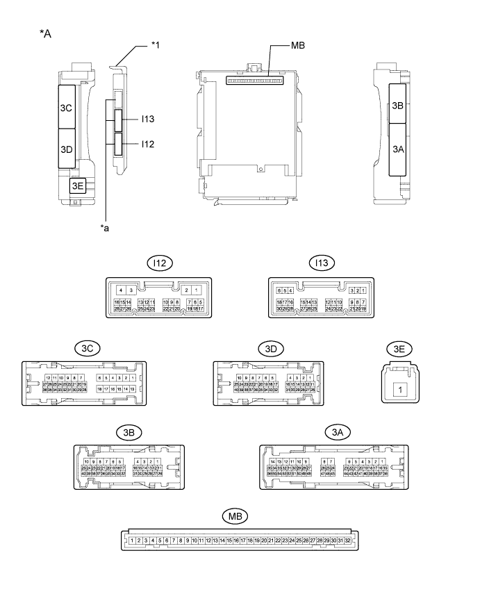
Text in Illustration *A Main Body ECU (Multiplex Network Body ECU) with 3 connectors - - *1 Main Body ECU (Multiplex Network Body ECU) - - *a 3 connectors - -
-
Disconnect the MB and I12 main body ECU (multiplex network body ECU) connectors.
-
Measure the voltage and resistance according to the value(s) in the table below.
Tech Tips
Measure the values on the wire harness side with the connectors disconnected.
Tester Connection Wiring Color Terminal Description Condition Specified Condition MB-11 (GND1) - Body ground - Ground Always Below 1 Ω I12-3 (GND2) - Body ground W-B - Body ground Ground Always Below 1 Ω MB-30 (BECU) - Body ground - Battery power supply Always 11 to 14 V MB-29 (ACC) - Body ground - ACC power supply Engine switch on (ACC) 11 to 14 V MB-29 (ACC) - Body ground - ACC power supply Engine switch off Below 1 V MB-31 (ALTB) - Body ground - Battery power supply Always 11 to 14 V MB-32 (IG) - Body ground - IG power supply Engine switch on (IG) 11 to 14 V MB-32 (IG) - Body ground - IG power supply Engine switch off Below 1 V If the result is not as specified, there may be a malfunction in the wire harness.
-
Reconnect the MB and I12 main body ECU (multiplex network body ECU) connectors.
-
Measure the voltage according to the value(s) in the table below.
Tester Connection Wiring Color Terminal Description Condition Specified Condition 3C-11 (ACT-) - Body ground G - Body ground Door lock motor unlock drive output (except driver door) Door control switch (power window regulator master switch assembly) or driver door key cylinder off Below 1 V 3C-11 (ACT-) - Body ground G - Body ground Door lock motor unlock drive output (except driver door) Door control switch (power window regulator master switch assembly) or driver door key cylinder unlocked 11 to 14 V 3C-12 (ACT+) - Body ground L - Body ground Door lock motor lock drive output (all doors) Door control switch (power window regulator master switch assembly) or driver door key cylinder off Below 1 V 3C-12 (ACT+) - Body ground L - Body ground Door lock motor lock drive output (all doors) Door control switch (power window regulator master switch assembly) or driver door key cylinder locked 11 to 14 V 3B-4 (ACTD) - Body ground GR - Body ground Driver door lock motor unlock drive output Door control switch (power window regulator master switch assembly) or driver door key cylinder off Below 1 V 3B-4 (ACTD) - Body ground GR - Body ground Driver door lock motor unlock drive output Door control switch (power window regulator master switch assembly) or driver door key cylinder unlocked 11 to 14 V 3C-15 (FLCY) - Body ground L - Body ground Front door LH courtesy light switch input Front door LH open Below 1 V 3C-15 (FLCY) - Body ground L - Body ground Front door LH courtesy light switch input Front door LH closed 11 to 14 V I13-19 (FRCY) - Body ground SB - Body ground Front door RH courtesy light switch input Front door RH open Below 1 V I13-19 (FRCY) - Body ground SB - Body ground Front door RH courtesy light switch input Front door RH closed 11 to 14 V I13-1 (LCTY) - Body ground P - Body ground Rear door LH courtesy light switch input Rear door LH open Below 1 V I13-1 (LCTY) - Body ground P - Body ground Rear door LH courtesy light switch input Rear door LH closed Pulse generation I13-6 (RCTY) - Body ground B - Body ground Rear door RH courtesy light switch input Rear door RH open Below 1 V I13-6 (RCTY) - Body ground B - Body ground Rear door RH courtesy light switch input Rear door RH closed Pulse generation I13-7 (LSFL) - Body ground V - Body ground Front door LH unlock detection switch input Front door LH unlocked Below 1 V I13-7 (LSFL) - Body ground V - Body ground Front door LH unlock detection switch input Front door LH locked Pulse generation I13-18 (LSFR) - Body ground W - Body ground Front door RH unlock detection switch input Front door RH unlocked Below 1 V I13-18 (LSFR) - Body ground W - Body ground Front door RH unlock detection switch input Front door RH locked Pulse generation 3A-53 (LSR) - Body ground Y - Body ground Rear door RH unlock detection switch input Rear door RH unlocked Below 1 V 3A-53 (LSR) - Body ground Y - Body ground Rear door RH unlock detection switch input Rear door RH locked Pulse generation 3C-17 (LSR) - Body ground LG - Body ground Rear door LH unlock detection switch input Rear door LH unlocked Below 1 V 3C-17 (LSR) - Body ground LG - Body ground Rear door LH unlock detection switch input Rear door LH locked Pulse generation 3D-22 (BZR) - Body ground BE - Body ground Wireless door lock buzzer signal Wireless door lock buzzer off Below 1 V 3D-22 (BZR) - Body ground BE - Body ground Wireless door lock buzzer signal Wireless door lock buzzer on Pulse generation If the result is not as specified, the main body ECU (multiplex network body ECU) or instrument panel junction block assembly may have a malfunction.
-
-
CHECK CERTIFICATION ECU (SMART KEY ECU ASSEMBLY)
-
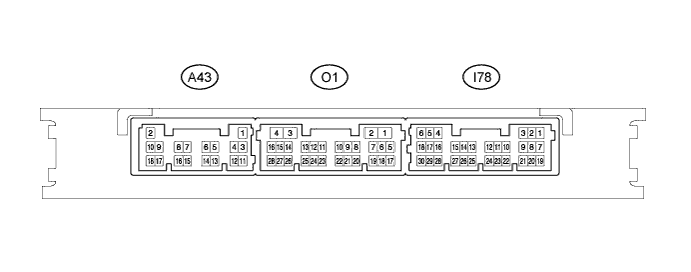
Disconnect the A43 certification ECU (smart key ECU assembly) connector.
-
Measure the resistance and voltage according to the value(s) in the table below.
Tech Tips
Measure the values on the wire harness side with the connector disconnected.
Tester Connection Wiring Color Terminal Description Condition Specified Condition A43-11 (E) - Body ground W - Body ground Ground Always Below 1 Ω A43-2 (+B) - Body ground W - Body ground Battery power supply Always 11 to 14 V A43-10 (CUTB) - Body ground L - Body ground Dark current cut fuse pin input signal Always 11 to 14 V
-
If the result is not as specified, there may be a malfunction in the wire harness.
-
-
Reconnect the A43 certification ECU (smart key ECU assembly) connector.
-
Measure the voltage according to the value(s) in the table below.
Tester Connection Wiring Color Terminal Description Condition Specified Condition I78-5 (IG) - A43-11 (E) LG - W IG power supply Engine switch on (IG) 11 to 14 V Engine switch off Below 1 V O1-6 (CSEL) - A43-11 (E) LG - W Communication channel switching circuit Engine switch off, all doors closed and electrical key transmitter sub-assembly switch not pressed → electrical key transmitter sub-assembly switch pressed → electrical key transmitter sub-assembly switch released Below 1 V → 4.5 to 6.0 V → Below 1 V O1-17 (RDAM) - A43-11 (E) Y - W RF Signal input circuit Engine switch off 11 to 14 V pulse generation at regular intervals O1-5 (RCO) - A43-11 (E) G - W Wireless tuner power supply output circuit Engine switch off, all doors closed and electrical key transmitter sub-assembly switch not pressed → electrical key transmitter sub-assembly switch pressed Below 1 V → 4.5 to 5.5 V
-
If the result is not as specified, the certification ECU (smart key ECU assembly) may have a malfunction.
-
-
-
CHECK DOOR CONTROL RECEIVER (w/o Side Turn Signal Light)

-
Disconnect the O25 door control receiver connector.
-
Measure the resistance and voltage according to the value(s) in the table below.
Tech Tips
Measure the values on the wire harness side with the connector disconnected.
Tester Connection Wiring Color Terminal Description Condition Specified Condition O25-7 (+B) - Body ground P - Body ground Battery (power supply) Always 10 to 16 V O25-12 (GND) - Body ground BR - Body ground Ground Always Below 1 Ω
-
If the result is not as specified, there may be a malfunction in the wire harness.
-
-
Reconnect the O25 door control receiver connector.
-
Measure the voltage according to the value(s) in the table below.
Tester Connection Wiring Color Terminal Description Condition Specified Condition O25-6 (CSEL) - O25-12 (GND) LG - BR Smart system receiving channel switching signal input Engine switch off, all doors closed and electrical key transmitter sub-assembly switch not pressed → electrical key transmitter sub-assembly switch pressed → electrical key transmitter sub-assembly switch released Below 1 V → 4.5 to 6.0 V → Below 1 V O25-2 (DATA) - O25-12 (GND) Y - BR Smart system recovery code output Engine switch off, all doors closed and electrical key transmitter sub-assembly switch not pressed → electrical key transmitter sub-assembly switch pressed → electrical key transmitter sub-assembly switch released Below 1 V → 10 to 16 V → Below 1 V O25-8 (+5) - O25-12 (GND) G - BR Receive mode switching signal input Engine switch off, all doors closed and electrical key transmitter sub-assembly switch not pressed → electrical key transmitter sub-assembly switch pressed Below 1 V → 4.5 to 5.5 V
-
If the result is not as specified, the certification ECU (smart key ECU assembly) may have a malfunction.
-
-
-
CHECK DOOR CONTROL RECEIVER (w/ Side Turn Signal Light)

-
Disconnect the O24 door control receiver connector.
-
Measure the resistance according to the value(s) in the table below.
Tech Tips
Measure the values on the wire harness side with the connector disconnected.
Tester Connection Wiring Color Terminal Description Condition Specified Condition O24-1 (GND) - Body ground BR - Body ground Ground Always Below 1 Ω
-
If the result is not as specified, there may be a malfunction in the wire harness.
-
-
Reconnect the O24 door control receiver connector.
-
Measure the voltage according to the value(s) in the table below.
Tester Connection Wiring Color Terminal Description Condition Specified Condition O24-2 (CSEL) - O24-1 (GND) LG - BR Smart system receiving channel switching signal input Engine switch off, all doors closed and electrical key transmitter sub-assembly switch not pressed → electrical key transmitter sub-assembly switch pressed → electrical key transmitter sub-assembly switch released Below 1 V → 4.5 to 6.0 V → Below 1 V O24-5 (DATA) - O24-1 (GND) Y - BR Smart system recovery code output Engine switch off, all doors closed and electrical key transmitter sub-assembly switch not pressed → electrical key transmitter sub-assembly switch pressed → electrical key transmitter sub-assembly switch released Below 1 V → 10 to 16 V → Below 1 V O24-4 (+5) - O24-1 (GND) G - BR Receive mode switching signal input Engine switch off, all doors closed and electrical key transmitter sub-assembly switch not pressed → electrical key transmitter sub-assembly switch pressed Below 1 V → 4.5 to 5.5 V
-
If the result is not as specified, the certification ECU (smart key ECU assembly) may have a malfunction.
-
-