CAN COMMUNICATION SYSTEM TERMINALS OF ECU

Note
-
After turning the ignition switch off, waiting time may be required before disconnecting the cable from the negative (-) battery terminal. Therefore, make sure to read the disconnecting the cable from the negative (-) battery terminal notices before proceeding with work Click here.
-
Turn the ignition switch off before measuring the resistances between CAN main bus lines and between CAN branch lines.
-
Turn the ignition switch off before inspecting CAN bus lines for a ground short.
-
Before measuring the resistance of the CAN bus, turn the ignition switch off and leave the vehicle for 1 minute or more without operating the key or any switches, or opening or closing the doors. After that, disconnect the cable from the negative (-) battery terminal and leave the vehicle for 1 minute or more before measuring the resistance.
-
This section describes the standard values for all CAN related components.
Tech Tips
-
Operating the ignition switch, any other switches or a door triggers related ECU and sensor communication on the CAN. This communication will cause the resistance value to change.
-
Even after DTCs are cleared, if a DTC is stored again after driving the vehicle for a while, the malfunction may be occurring due to vibration of the vehicle. In such a case, wiggling the ECUs or wire harness while performing the inspection below may help determine the cause of the malfunction.
-
CAN NO. 1 JUNCTION CONNECTOR
-
Check the CAN No. 1 junction connector.
Tech Tips
Connectors that connect to the CAN junction connector can be distinguished by the color of their CAN bus lines. When the connectors have been disconnected from the CAN junction connector, reconnecting the connectors to non-original positions on the CAN junction connector does not affect system performance. However, it is preferred to reconnect the connectors to their original positions to avoid negative effects on the wiring such as tension on the wire harnesses, and to make future maintenance easier.
-
Connection diagram
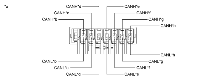
Text in Illustration *a Component with harness connected
(CAN No. 1 Junction Connector)
*b to Main Body ECU (Multiplex Network Body ECU)
(for V Bus)
*c to Steering Sensor
(for V Bus)
*d to Airbag Sensor Assembly
(for V Bus)
*e to DLC3 *f
-
to Power Steering ECU with Motor Assembly (for 2AR-FE)
-
to Power Steering ECU Assembly (for 2GR-FE)
(for V Bus)
*g to Combination Meter Assembly
(for V Bus)
*h to CAN No. 2 Junction Connector
(for V Bus)
-
-
Check the connection diagram of the components which are connected to the CAN No. 1 junction connector.
Terminal No. (Symbol) Wiring Color Connected to (Applicable Bus) I95-1 (CANH) P Main body ECU (Multiplex network body ECU)
(for V bus)
I95-2 (CANL) W I97-1 (CANH) V Steering sensor
(for V bus)
I97-2 (CANL) W I103-1 (CANH) Y Airbag sensor assembly
(for V bus)
I103-2 (CANL) W I96-1 (CANH) L DLC3 I96-2 (CANL) W I100-1 (CANH) G
-
Power steering ECU with motor assembly*1
-
Power steering ECU assembly*2
(for V bus)
I100-2 (CANL) W I94-1 (CANH) R Combination meter assembly
(for V bus)
I94-2 (CANL) W I93-1 (CANH) B CAN No. 2 junction connector
(for V bus)
I93-2 (CANL) W
-
*1: for 2AR-FE
-
*2: for 2GR-FE
-
-
-
-
CAN NO. 2 JUNCTION CONNECTOR
-
Check the CAN No. 2 junction connector.
Tech Tips
Connectors that connect to the CAN junction connector can be distinguished by the color of their CAN bus lines. When the connectors have been disconnected from the CAN junction connector, reconnecting the connectors to non-original positions on the CAN junction connector does not affect system performance. However, it is preferred to reconnect the connectors to their original positions to avoid negative effects on the wiring such as tension on the wire harnesses, and to make future maintenance easier.
-
Connection diagram
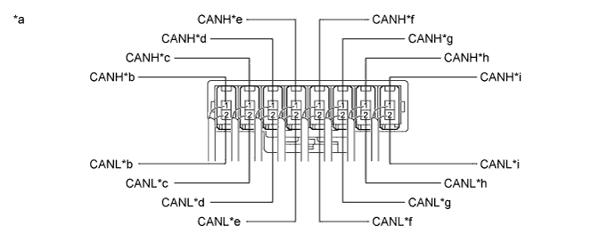
Text in Illustration *a Component with harness connected
(CAN No. 2 Junction Connector)
*b
-
to Clearance Warning ECU Assembly (w/ Intuitive Parking Assist System)
-
to Tire Pressure Warning ECU and Receiver (for Tire Pressure Warning System with Tire Inflation Pressure Display Function)
(for V Bus)
*c to ECM
(for V Bus)
*d to Air Conditioning Amplifier Assembly
(for V Bus)
*e to Brake Actuator Assembly (Skid Control ECU)
(for V Bus)
*f to Smart Key ECU Assembly (Certification ECU) (w/ Smart Key System)
(for V Bus)
*g to Network Gateway ECU (w/ Network Gateway ECU)
(for V Bus)
*h
-
to Navigation Receiver Assembly (for Navigation Receiver Type)
-
to Radio and Display Receiver Assembly (for Radio and Display Type)
(for V Bus)
*i to CAN No. 1 Junction Connector
(for V Bus)
- - -
-
Check the connection diagram of the components which are connected to the CAN No. 2 junction connector.
Terminal No. (Symbol) Wiring Color Connected to I111-1 (CANH) BE
-
Clearance warning ECU assembly*1
-
Tire pressure warning ECU and receiver*2
(for V bus)
I111-2 (CANL) W I104-1 (CANH) P ECM
(for V bus)
I104-2 (CANL) W I102-1 (CANH) V Air conditioning amplifier assembly
(for V bus)
I102-2 (CANL) W I105-1 (CANH) Y Brake actuator assembly (Skid control ECU)
(for V bus)
I105-2 (CANL) W I106-1 (CANH) L Smart key ECU assembly (Certification ECU)*3
(for V bus)
I106-2 (CANL) W I108-1 (CANH) G Network gateway ECU*4
(for V bus)
I108-2 (CANL) W I107-1 (CANH) R
-
Navigation receiver assembly*5
-
Radio and display receiver assembly*6
(for V bus)
I107-2 (CANL) W I101-1 (CANH) B CAN No. 1 junction connector
(for V bus)
I101-2 (CANL) W
-
*1: w/ Intuitive Parking Assist System
-
*2: for Tire Pressure Warning System with Tire Inflation Pressure Display Function
-
*3: w/ Smart Key System
-
*4: w/ Network Gateway ECU
-
*5: for Navigation Receiver Type
-
*6: for Radio and Display Type
-
-
-
-
CAN NO. 3 JUNCTION CONNECTOR (w/ Network Gateway ECU)
-
Check the CAN No. 3 junction connector.
-

Text in Illustration *a Front view of wire harness connector
(to CAN No. 3 Junction Connector)
*b to Blind Spot Monitor Sensor RH (w/ Blind Spot Monitor System)
(for Sub Bus 2)
*c to CAN No. 6 Junction Connector
(for Sub Bus 2)
*d to CAN No. 7 Junction Connector
(for Sub Bus 2)
Connection diagram
-
Check the connection diagram of the components which are connected to the CAN No. 3 junction connector.
Terminal No. (Symbol) Wiring Color Connected to O30-9 (CANH) R Blind spot monitor sensor RH*
(for Sub bus 2)
O30-20 (CANL) B O30-10 (CANH) G CAN No. 6 junction connector
(for Sub bus 2)
O30-21 (CANL) B O30-11 (CANH) V CAN No. 7 junction connector
(for Sub bus 2)
O30-22 (CANL) B
-
*: w/ Blind Spot Monitor System
-
-
-
-
CAN NO. 5 JUNCTION CONNECTOR (w/ Network Gateway ECU)
-
Check the CAN No. 5 junction connector.
-
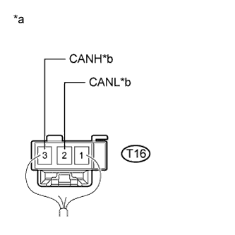
Text in Illustration *a Rear view of wire harness connector
(to CAN No. 5 Junction Connector)
*b to CAN No. 6 Junction Connector
(for Sub Bus 2)
Connection diagram
-
Check the connection diagram of the components which are connected to the CAN No. 5 junction connector.
Terminal No. (Symbol) Wiring Color Connected to T16-3 (CANH) L CAN No. 6 junction connector
(for Sub bus 2)
T16-2 (CANL) B
-
-
-
CAN NO. 6 JUNCTION CONNECTOR (w/ Network Gateway ECU)
-
Check the CAN No. 6 junction connector.
-
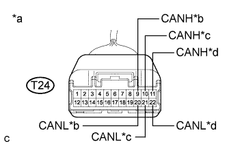
Text in Illustration *a Front view of wire harness connector
(to CAN No. 6 Junction Connector)
*b to CAN No. 5 Junction Connector
(for Sub Bus 2)
*c to Rear Television Camera Assembly (w/ Parking Assist Monitor System)
(for Sub Bus 2)
*d to CAN No. 3 Junction Connector
(for Sub Bus 2)
Connection diagram
-
Check the connection diagram of the components which are connected to the CAN No. 6 junction connector.
Terminal No. (Symbol) Wiring Color Connected to T24-9 (CANH) L CAN No. 5 junction connector
(for Sub bus 2)
T24-20 (CANL) B T24-10 (CANH) V Rear television camera assembly*
(for Sub bus 2)
T24-21 (CANL) B T24-11 (CANH) G CAN No. 3 junction connector
(for Sub bus 2)
T24-22 (CANL) B
-
*: w/ Parking Assist Monitor System
-
-
-
-
CAN NO. 7 JUNCTION CONNECTOR (w/ Network Gateway ECU)
-
Check the CAN No. 7 junction connector.
Tech Tips
Connectors that connect to the CAN junction connector can be distinguished by the color of their CAN bus lines. When the connectors have been disconnected from the CAN junction connector, reconnecting the connectors to non-original positions on the CAN junction connector does not affect system performance. However, it is preferred to reconnect the connectors to their original positions to avoid negative effects on the wiring such as tension on the wire harnesses, and to make future maintenance easier.
-
Connection diagram
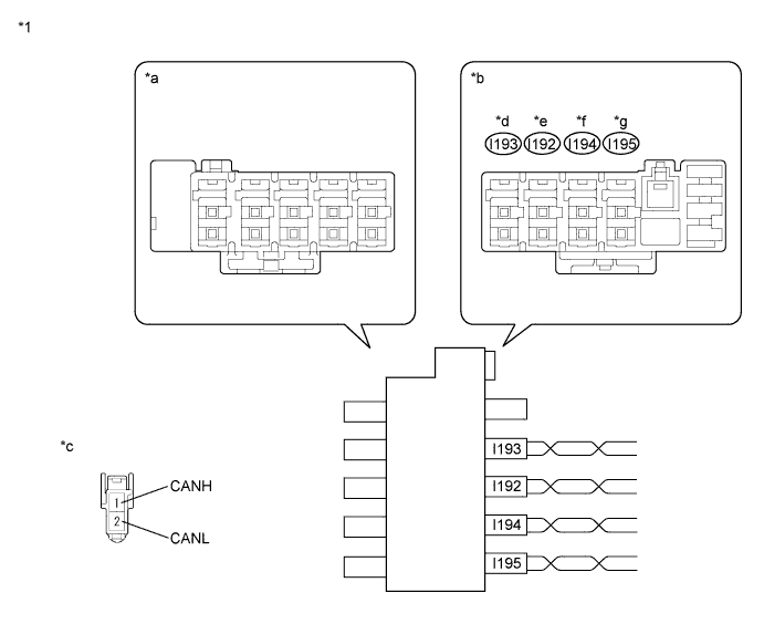
Text in Illustration *1 CAN No. 7 Junction Connector - - *a Junction Connector A Side *b Junction Connector B Side *c Front view of wire harness connector
(to CAN No. 7 Junction Connector)
*d to CAN No. 3 Junction Connector
(for Sub Bus 2)
*e to Network Gateway ECU (w/ Parking Assist Monitor System)
(for Sub Bus 2)
*f to Driving support ECU assembly (w/ Pre-collision System)
(for Sub Bus 2)
*g to CAN No. 8 junction connector (w/o Parking Assist Monitor System)
(for Sub Bus 2)
- - -
Check the connection diagram of the components which are connected to the CAN No. 7 junction connector.
Terminal No. (Symbol) Wiring Color Connected to I192-1 (CANH) B Network gateway ECU*3
(for Sub bus 2)
I192-2 (CANL) LG I193-1 (CANH) G CAN No. 3 junction connector
(for Sub bus 2)
I193-2 (CANL) LG I194-1 (CANH) L Driving support ECU assembly*2
(for Sub bus 2)
I194-2 (CANL) LG I195-1 (CANH) R CAN No. 8 junction connector*1
(for Sub bus 2)
I195-2 (CANL) LG
-
*1: w/o Parking Assist Monitor System
-
*2: w/ Pre-collision System
-
*3: w/ Parking Assist Monitor System
-
-
-
-
CAN NO. 8 JUNCTION CONNECTOR (w/ Network Gateway ECU without Parking Assist Monitor System)
-
Check the CAN No. 8 junction connector.
-
Connection diagram
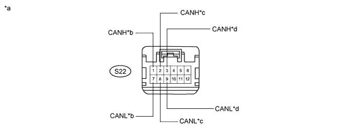
Text in Illustration *a Front view of wire harness connector
(to CAN No. 8 Junction Connector)
*b to Lane Departure Warning Camera (w/ Pre-collision System)
(for Sub Bus 2)
*c to CAN No. 7 Junction Connector
(for Sub Bus 2)
*d to Network Gateway ECU
(for Sub Bus 2)
-
Check the connection diagram of the components which are connected to the CAN No. 8 junction connector.
Terminal No. (Symbol) Wiring Color Connected to S22-1 (CANH) V Lane departure warning camera*
(for Sub bus 2)
S22-7 (CANL) LG S22-2 (CANH) R CAN No. 7 junction connector
(for Sub bus 2)
S22-8 (CANL) LG S22-3 (CANH) B Network gateway ECU
(for Sub bus 2)
S22-9 (CANL) LG
-
*: w/ Pre-collision System
-
-
-
-
DLC3
-
Disconnect the cable from the negative (-) battery terminal.
-
Measure the resistance according to the value(s) in the table below.
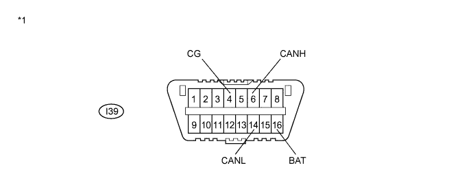
Text in Illustration *1 DLC3 - -
-
-
ECM (for 2GR-FE)
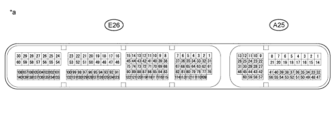
Text in Illustration *a Component without harness connected
(ECM)
- -
-
Disconnect the cable from the negative (-) battery terminal.
-
Disconnect the A25 and E26 ECM connectors.
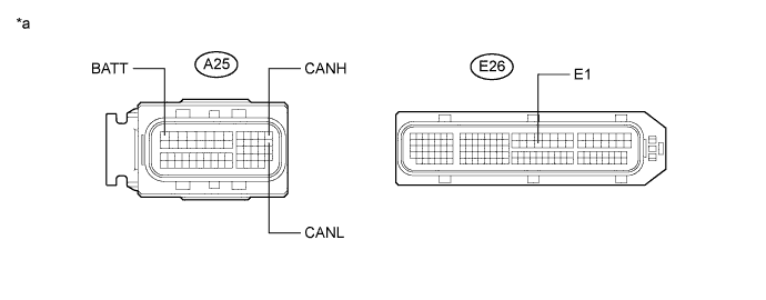
Text in Illustration *a Front view of wire harness connector
(to ECM)
- - -
Measure the resistance according to the value(s) in the table below.
-
-
ECM (for 2AR-FE)
Text in Illustration *a Component without harness connected
(ECM)
- -
-
Disconnect the cable from the negative (-) battery terminal.
-
Disconnect the A25 and E26 ECM connectors.
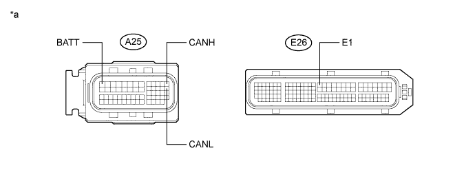
Text in Illustration *a Front view of wire harness connector
(to ECM)
- - -
Measure the resistance according to the value(s) in the table below.
-
-
COMBINATION METER ASSEMBLY (w/o Multi-information Display)
Text in Illustration *a Component without harness connected
(Combination Meter Assembly)
- -
-
Disconnect the cable from the negative (-) battery terminal.
-
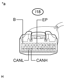
Text in Illustration *a Front view of wire harness connector
(to Combination Meter Assembly)
Disconnect the I18 combination meter assembly connector.
-
Measure the resistance according to the value(s) in the table below.
-
-
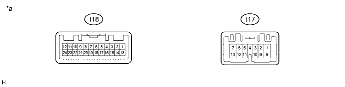
COMBINATION METER ASSEMBLY (w/ Multi-information Display)
Text in Illustration *a Component without harness connected
(Combination Meter Assembly)
- -
-
Disconnect the cable from the negative (-) battery terminal.
-
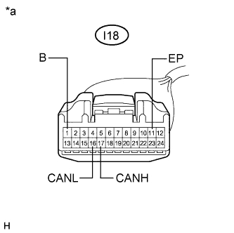
Text in Illustration *a Front view of wire harness connector
(to Combination Meter Assembly)
Disconnect the I18 combination meter assembly connector.
-
Measure the resistance according to the value(s) in the table below.
-
-
MAIN BODY ECU (MULTIPLEX NETWORK BODY ECU)
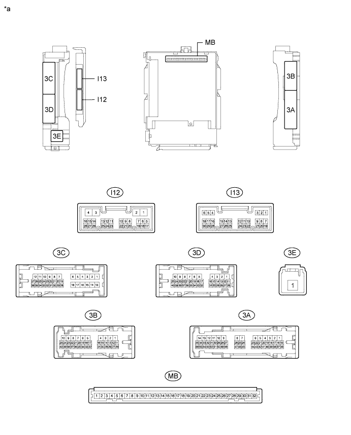
Text in Illustration *a Component without harness connected
(Main Body ECU (Multiplex Network Body ECU))
- -
-
Disconnect the cable from the negative (-) battery terminal.
-
Disconnect the I13 main body ECU (multiplex network body ECU) connector.
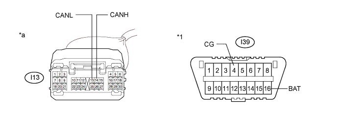
Text in Illustration *1 DLC3 - - *a Front view of wire harness connector
(to Main Body ECU (Multiplex Network Body ECU))
- - -
Measure the resistance according to the value(s) in the table below.
-
-
BRAKE ACTUATOR ASSEMBLY (SKID CONTROL ECU) (for 2AR-FE (w/ Dynamic Radar Cruise Control System), 2GR-FE)

Text in Illustration *a Component without harness connected
(Brake Actuator Assembly (Skid Control ECU))
- -
-
Disconnect the cable from the negative (-) battery terminal.
-

Text in Illustration *a Front view of wire harness connector
(to Brake Actuator Assembly (Skid Control ECU))
Disconnect the A94 brake actuator assembly (skid control ECU) connector.
-
Measure the resistance according to the value(s) in the table below.
-
-
BRAKE ACTUATOR ASSEMBLY (SKID CONTROL ECU) (for 2AR-FE (w/o Dynamic Radar Cruise Control System))
Text in Illustration *a Component without harness connected
(Brake Actuator Assembly (Skid Control ECU))
- -
-
Disconnect the cable from the negative (-) battery terminal.
-
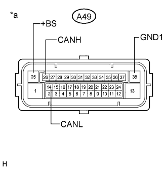
Text in Illustration *a Front view of wire harness connector
(to Brake Actuator Assembly (Skid Control ECU))
Disconnect the A49 brake actuator assembly (skid control ECU) connector.
-
Measure the resistance according to the value(s) in the table below.
-
-
STEERING SENSOR
-
Disconnect the cable from the negative (-) battery terminal.
-
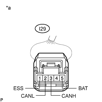
Text in Illustration *a Front view of wire harness connector
(to Steering Sensor)
Disconnect the I29 steering sensor connector.
-
Measure the resistance according to the value(s) in the table below.
-
-
POWER STEERING ECU WITH MOTOR ASSEMBLY (for 2AR-FE)
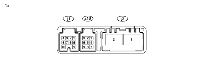
Text in Illustration *a Component without harness connected
(Power Steering ECU with Motor Assembly)
- -
-
Disconnect the cable from the negative (-) battery terminal.
-
Disconnect the j1 and j2 power steering ECU with motor assembly connectors.
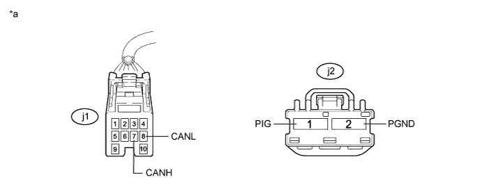
Text in Illustration *a Front view of wire harness connector
(to Power Steering ECU with Motor Assembly)
- - -
Measure the resistance according to the value(s) in the table below.
-
-
POWER STEERING ECU ASSEMBLY (for 2GR-FE)
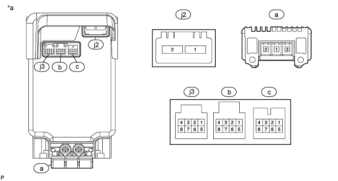
Text in Illustration *a Component without harness connected
(Power Steering ECU Assembly)
- -
-
Disconnect the cable from the negative (-) battery terminal.
-
Disconnect the j2 and j3 power steering ECU assembly connectors.
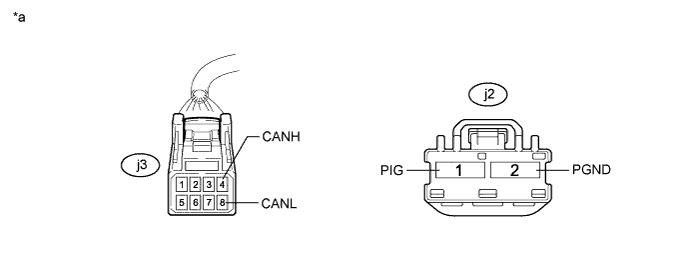
Text in Illustration *a Front view of wire harness connector
(to Power Steering ECU Assembly)
- - -
Measure the resistance according to the value(s) in the table below.
-
-
AIRBAG SENSOR ASSEMBLY
-
Disconnect the cable from the negative (-) battery terminal.
-
Disconnect the I47 airbag sensor assembly connector.
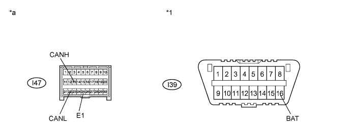
Text in Illustration *1 DLC3 - - *a Front view of wire harness connector
(to Airbag Sensor Assembly)
- - -
Measure the resistance according to the value(s) in the table below.
-
-
SMART KEY ECU ASSEMBLY (CERTIFICATION ECU) (w/ Smart Key System)
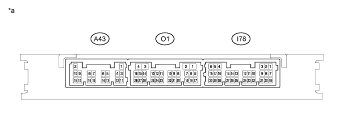
Text in Illustration *a Component without harness connected
(Smart Key ECU Assembly (Certification ECU))
- -
-
Disconnect the cable from the negative (-) battery terminal.
-
Disconnect the A43 and I78 smart key ECU assembly connectors.
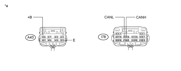
Text in Illustration *a Rear view of wire harness connector
(to Smart Key ECU Assembly (Certification ECU))
- - -
Measure the resistance according to the value(s) in the table below.
-
-
RADIO AND DISPLAY RECEIVER ASSEMBLY (w/ DVD Player)
Text in Illustration *a Component without harness connected
(Radio and Display Receiver Assembly)
- -
-
Disconnect the cable from the negative (-) battery terminal.
-
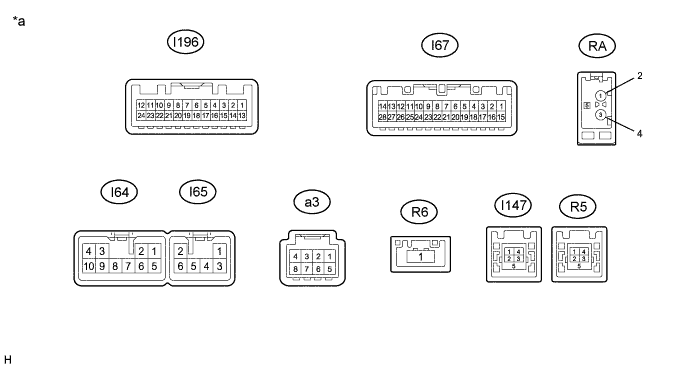
Disconnect the I67 and I64 radio and display receiver assembly connectors.

Text in Illustration *a Front view of wire harness connector
(to Radio and Display Receiver Assembly)
- - -
Measure the resistance according to the value(s) in the table below.
-
-
RADIO AND DISPLAY RECEIVER ASSEMBLY (w/o DVD Player)
Text in Illustration *a Component without harness connected
(Radio and Display Receiver Assembly)
- -
-
Disconnect the cable from the negative (-) battery terminal.
-
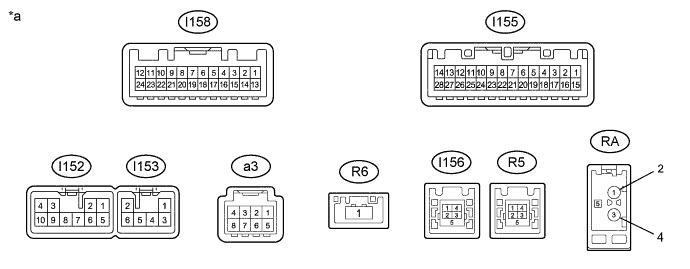
Disconnect the I155 and I152 radio and display receiver assembly connectors.
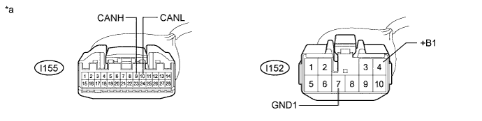
Text in Illustration *a Front view of wire harness connector
(to Radio and Display Receiver Assembly)
- - -
Measure the resistance according to the value(s) in the table below.
-
-
NAVIGATION RECEIVER ASSEMBLY (for Navigation Receiver Type)
Text in Illustration *a Component without harness connected
(Navigation Receiver Assembly)
- -
-
Disconnect the cable from the negative (-) battery terminal.
-
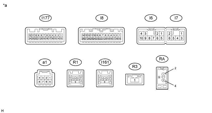
Disconnect the I8 and I6 navigation receiver assembly connectors.
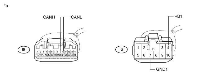
Text in Illustration *a Front view of wire harness connector
(to Navigation Receiver Assembly)
- - -
Measure the resistance according to the value(s) in the table below.
-
-
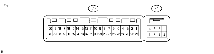
AIR CONDITIONING AMPLIFIER ASSEMBLY (for Automatic Air Conditioning System)
Text in Illustration *a Component without harness connected
(Air Conditioning Amplifier Assembly)
- -
-
Disconnect the cable from the negative (-) battery terminal.
-
Disconnect the I77 air conditioning amplifier assembly connector.
Text in Illustration *a Front view of wire harness connector
(to Air Conditioning Amplifier Assembly)
- - -
Measure the resistance according to the value(s) in the table below.
-
-
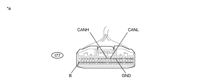
AIR CONDITIONING AMPLIFIER ASSEMBLY (for Manual Air Conditioning System)
Text in Illustration *a Component without harness connected
(Air Conditioning Amplifier Assembly)
- -
-
Disconnect the cable from the negative (-) battery terminal.
-
Disconnect the I77 air conditioning amplifier assembly connector.
Text in Illustration *a Front view of wire harness connector
(to Air Conditioning Amplifier Assembly)
- - -
Measure the resistance according to the value(s) in the table below.
-
-
CLEARANCE WARNING ECU ASSEMBLY (w/ Intuitive Parking Assist System)
-
Disconnect the cable from the negative (-) battery terminal.
-
Disconnect the I82 clearance warning ECU assembly connector.
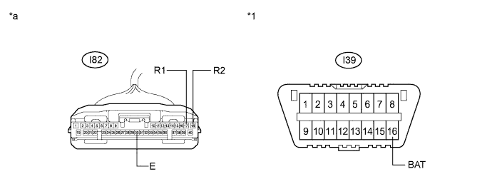
Text in Illustration *1 DLC3 - - *a Front view of wire harness connector
(to Clearance Warning ECU Assembly)
- - -
Measure the resistance according to the value(s) in the table below.
-
-
NETWORK GATEWAY ECU (w/ Network Gateway ECU)
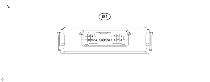
Text in Illustration *a Component without harness connected
(Network Gateway ECU)
- -
-
Disconnect the cable from the negative (-) battery terminal.
-
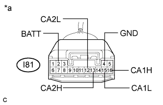
Text in Illustration *a Front view of wire harness connector
(to Network Gateway ECU)
Disconnect the I81 network gateway ECU connector.
-
Measure the resistance according to the value(s) in the table below.
-
-
BLIND SPOT MONITOR SENSOR RH (w/ Blind Spot Monitor System)

Text in Illustration *a Component without harness connected
(Blind Spot Monitor Sensor RH)
- -
-
Disconnect the cable from the negative (-) battery terminal.
-
Disconnect the O28 blind spot monitor sensor RH connector.
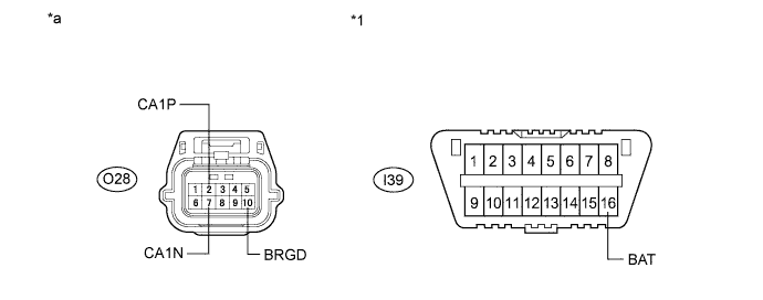
Text in Illustration *1 DLC3 - - *a Front view of wire harness connector
(to Blind Spot Monitor Sensor RH)
- - -
Measure the resistance according to the value(s) in the table below.
-
-
TIRE PRESSURE WARNING ECU AND RECEIVER (for Tire Pressure Warning System with Tire Inflation Pressure Display Function)
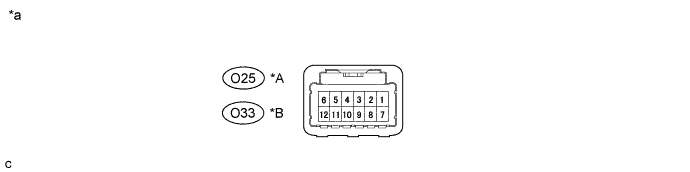
Text in Illustration *A w/o Intuitive Parking Assist System with Smart Key System *B w/o Intuitive Parking Assist System without Smart Key System *a Component without harness connected
(Tire Pressure Warning ECU and Receiver)
- -
-
Disconnect the cable from the negative (-) battery terminal.
-
Disconnect the tire pressure warning ECU and receiver connector.
Text in Illustration *A w/o Intuitive Parking Assist System with Smart Key System *B w/o Intuitive Parking Assist System without Smart Key System *1 DLC3 - - *a Front view of wire harness connector
(to Tire Pressure Warning ECU and Receiver)
- - -
Measure the resistance according to the value(s) in the table below.
-
-
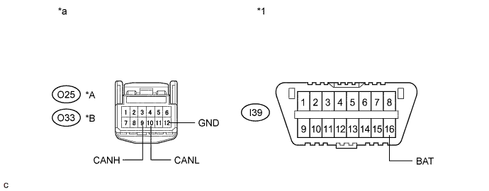
REAR TELEVISION CAMERA ASSEMBLY (w/ Parking Assist Monitor System)
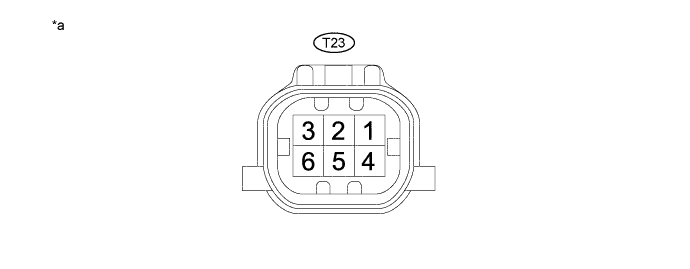
Text in Illustration *a Component without harness connected
(Rear Television Camera Assembly)
- -
-
Disconnect the cable from the negative (-) battery terminal.
-
Disconnect the T23 rear television camera assembly connector.
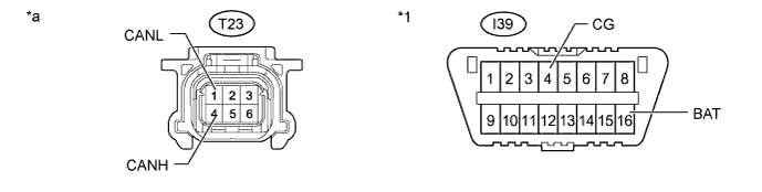
Text in Illustration *1 DLC3 - - *a Front view of wire harness connector
(to Rear Television Camera Assembly)
- - -
Measure the resistance according to the value(s) in the table below.
-
-
DRIVING SUPPORT ECU ASSEMBLY (w/ Pre-collision System)
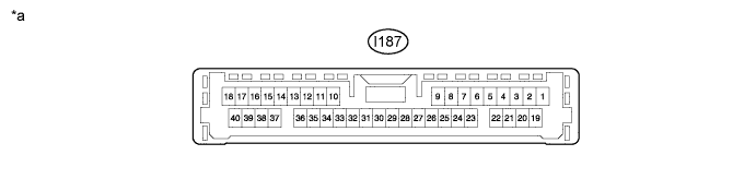
Text in Illustration *a Component without harness connected
(Driving Support ECU Assembly)
- -
-
Disconnect the cable from the negative (-) battery terminal.
-
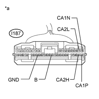
Text in Illustration *a Front view of wire harness connector
(to Driving Support ECU Assembly)
Disconnect the I187 driving support ECU assembly connector.
-
Measure the resistance according to the value(s) in the table below.
-
-
LANE DEPARTURE WARNING CAMERA (w/ Pre-collision System)
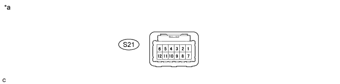
Text in Illustration *a Component without harness connected
(Lane Departure Warning Camera)
- -
-
Disconnect the cable from the negative (-) battery terminal.
-
Disconnect the S21 lane departure warning camera connector.
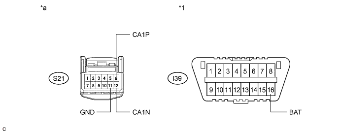
Text in Illustration *1 DLC3 - - *a Front view of wire harness connector
(to Lane Departure Warning Camera)
- - -
Measure the resistance according to the value(s) in the table below.
-
-
MILLIMETER WAVE RADAR SENSOR ASSEMBLY (w/ Pre-collision System)
-
Disconnect the cable from the negative (-) battery terminal.
-
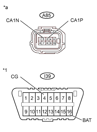
Text in Illustration *1 DLC3 *a Front view of wire harness connector
(to Millimeter Wave Radar Sensor Assembly)
Disconnect the A85 millimeter wave radar sensor assembly connector.
-
Measure the resistance according to the value(s) in the table below.
-