SAFETY CONNECT SYSTEM, Diagnostic DTC:B1570

| DTC Code | DTC Name |
|---|---|
| B1570 | Manual (SOS) Switch Red Indicator Malfunction |
DESCRIPTION
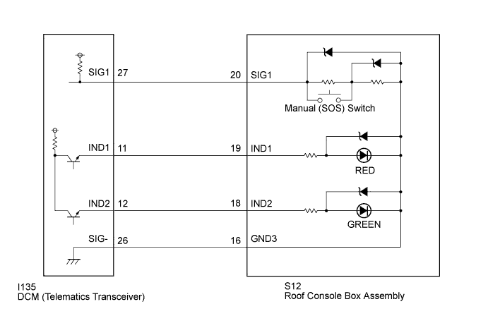
This DTC is stored when the DCM (Telematics Transceiver) detects an open or short in the manual (SOS) switch red indicator circuit of the manual (SOS) switch.
The manual (SOS) switch red indicator illuminates for 2 seconds and goes off when the engine switch is turned on (IG). If a malfunction in the safety connect system is detected, the manual (SOS) switch red indicator will illuminate.
However, the manual (SOS) switch red indicator may not illuminate when this DTC is set.
Tech Tips
The manual (SOS) switch red indicator may not operate to indicate another DTC has been set, therefore voice guidance is provided.
| DTC No. | DTC Detection Condition | Trouble Area |
|---|---|---|
| B1570 | Current for manual (SOS) switch red indicator reaches malfunction criteria for 10 seconds when engine switch is on (IG). |
|
WIRING DIAGRAM
INSPECTION PROCEDURE
PROCEDURE
-
CHECK DTC
-
Turn the engine switch off.
-
Connect the Techstream to the DLC3.
-
Turn the engine switch on (IG) and wait for 10 seconds.
-
Turn the Techstream on.
-
Perform "Health Check" and check for current DTCs Click here.
Result Result Proceed to DTC B1570, B1571 and B15C5 are output A DTC B1570 is output
(DTC B1571 and B15C5 are not output)
B
B 
INSPECT ROOF CONSOLE BOX ASSEMBLY (MANUAL (SOS) SWITCH RED INDICATOR CONDITION) Click here
A 
-
-
INSPECT ROOF CONSOLE BOX ASSEMBLY (RED INDICATOR)
-
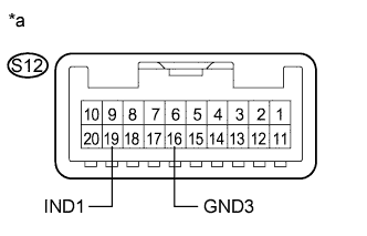
Text in Illustration *a Component without harness connected
(Roof Console Box Assembly)
Disconnect the S12 roof console box assembly connector.
-
Connect 2 dry-cell batteries (1.5 V each) in series.
-
Connect the positive (+) lead to terminal S12-19 (IND1) and the negative (-) lead to terminal S12-16 (GND3) of the roof console box assembly connectors.
-
Check if the illumination for the manual (SOS) switch red indicator comes on.
OK Red indicator comes on.
NG 
REPLACE ROOF CONSOLE BOX ASSEMBLY Click here
OK
-
-
CHECK HARNESS AND CONNECTOR (DCM (TELEMATICS TRANSCEIVER) - ROOF CONSOLE BOX ASSEMBLY)
-
Disconnect the I135 DCM (Telematics Transceiver) connector.
-
Disconnect the S12 roof console box assembly connector.
-
Measure the resistance according to the value(s) in the table below.
Standard Resistance Tester Connection Condition Specified Condition I135-26 (SIG-) - S12-16 (GND3) Always Below 1 Ω I135-26 (SIG-) - Body ground Always 10 kΩ or higher
NG
REPAIR OR REPLACE HARNESS OR CONNECTOR
OK
-
-
REPLACE DCM (TELEMATICS TRANSCEIVER)
-
Replace the DCM (Telematics Transceiver) Click here.
Note
-
The engine switch must be off.
-
Do not swap the DCM (Telematics Transceiver) with one from another vehicle.
-
NEXT 
PERFORM DCM ACTIVATION Click here
-
-
INSPECT ROOF CONSOLE BOX ASSEMBLY (MANUAL (SOS) SWITCH RED INDICATOR CONDITION)
-
Confirm the red indicator status after the engine switch is turned on (IG) Click here.
Result Result Proceed to Red indicator remains off. A Red indicator remains on. B
B
REPLACE DCM (TELEMATICS TRANSCEIVER) Click here
A
-
-
INSPECT ROOF CONSOLE BOX ASSEMBLY (RED INDICATOR INPUT VOLTAGE)
-
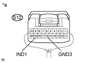
Text in Illustration *a Component with harness connected
(Roof Console Box Assembly)
Remove the roof console box assembly but do not disconnect the connectors Click here.
-
Connect the positive lead of a voltmeter to terminal S12-19 (IND1), and the negative lead to terminal S12-16 (GND3).
-
Measure the voltage.
Standard 1.0 to 8.5 V for 2 seconds after the engine switch is turned on (IG). 0 V when the engine switch is off.
NG
INSPECT DCM (TELEMATICS TRANSCEIVER) (RED INDICATOR OUTPUT VOLTAGE) Click here
OK
REPLACE ROOF CONSOLE BOX ASSEMBLY Click here
-
-
INSPECT DCM (TELEMATICS TRANSCEIVER) (RED INDICATOR OUTPUT VOLTAGE)
-
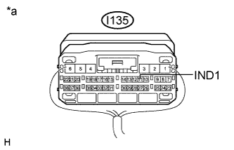
Text in Illustration *a Component with harness connected
(DCM (Telematics Transceiver))
Remove the DCM (Telematics Transceiver) but do not disconnect the connectors Click here.
-
Connect the positive lead of a voltmeter to terminal I135-11 (IND1), and the negative lead to body ground.
-
Measure the voltage.
Standard 1.0 to 8.5 V for 2 seconds after the engine switch is turned on (IG). 0 V when the engine switch is off.
NG
CHECK HARNESS AND CONNECTOR (DCM (TELEMATICS TRANSCEIVER) - BODY GROUND) Click here
OK
REPAIR OR REPLACE HARNESS OR CONNECTOR
-
-
CHECK HARNESS AND CONNECTOR (DCM (TELEMATICS TRANSCEIVER) - BODY GROUND)
-
Text in Illustration *a Component with harness connected
(DCM (Telematics Transceiver))
Remove the DCM (Telematics Transceiver) but do not disconnect the connectors Click here.
-
Measure the resistance according to the value(s) in the table below.
Standard Resistance Tester Connection Condition Specified Condition I135-11 (IND1) - Body ground Always 10 kΩ or higher
NG
REPAIR OR REPLACE HARNESS OR CONNECTOR
OK
-
-
REPLACE DCM (TELEMATICS TRANSCEIVER)
-
Replace the DCM (Telematics Transceiver) Click here.
Note
-
The engine switch must be off.
-
Do not swap the DCM (Telematics Transceiver) with one from another vehicle.
-
NEXT
PERFORM DCM ACTIVATION Click here
-