SAFETY CONNECT SYSTEM TERMINALS OF ECU

-
CHECK DCM (TELEMATICS TRANSCEIVER)
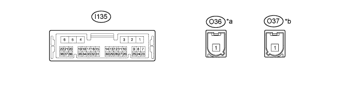
Text in Illustration *a Connector Color: Blue (to Telephone Antenna) *b Connector Color: Gray (to GPS Antenna) Terminal No. (Symbol) Wiring Color Terminal Description Condition Specified Condition I135-1 (+B) - I135-4 (E) G - BR Battery power supply Always 11 to 14 V I135-2 (SPI+) - I135-4 (E) Y - BR Sound signal Audio system playing A waveform synchronized with sound is output I135-3 (SPI-) - I135-4 (E) P - BR Sound signal Audio system playing A waveform synchronized with sound is output I135-4 (E) - Body ground BR - Body ground Ground Always Below 1 V I135-5 (SPO+) - I135-4 (E) LG - BR Sound signal Audio system playing, or Emergency call mode A waveform synchronized with sound is output I135-6 (SPO-) - I135-4 (E) L - BR Sound signal Audio system playing, or Emergency call mode A waveform synchronized with sound is output I135-7 (IG2) - I135-4 (E) LG - BR IG power supply Engine switch on (IG) 11 to 14 V Engine switch off Below 1 V I135-8 (ACC) - I135-4 (E) GR - BR ACC power supply Engine switch on (ACC) 11 to 14 V Engine switch off Below 1 V I135-10 (SPDP) - I135-4 (E) V - BR Vehicle speed signal See "Check Vehicle Signal" Click here
- I135-11 (IND1) - I135-4 (E) G - BR Manual (SOS) switch red indicator illumination signal For 2 seconds after turning the Engine switch on (IG) 1 to 8.5 V Engine switch off Below 1 V I135-12 (IND2) - I135-4 (E) GR - BR Manual (SOS) switch green indicator illumination signal For 2 seconds after turning the Engine switch on (IG) 1 to 8.5 V Engine switch off Below 1 V I135-13 (BBI-) W BUB (Back-Up Battery) power supply - - I135-17 (MUTE) - I135-4 (E) R - BR Mute signal Audio system playing 3.5 V or higher Emergency call mode Below 1 V I135-18 (MCO+) - I135-4 (E) R - BR Sent microphone voice signal See "Check Microphone & Voice Recognition" Click here
- I135-19 (MCO-) - I135-4 (E) G - BR Sent microphone voice signal See "Check Microphone & Voice Recognition" Click here
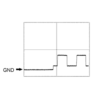
- I135-20 (CTR1) V BUB (Back-Up Battery) control line - - I135-21 (CTR2) L BUB (Back-Up Battery) control line - - I135-23 (ILL+) - I135-4 (E) G - BR Illumination signal Light control switch off Below 1 V Light control switch tail or head 11 to 14 V I135-24 (GSW) - I135-4 (E) B - BR Collision detection signal Engine switch on (IG) Pulse generation
(Refer to waveform 1)
I135-25 (SIL) GR Serial communication line - - I135-26 (SIG-) - I135-4 (E) V - BR Ground Always Below 1 V I135-27 (SIG1) - I135-4 (E) L - BR Manual (SOS) switch condition signal Manual (SOS) switch not pressed 1.5 to 2.0 V Manual (SOS) switch pressed 0.5 to 0.8 V I135-30 (BBI+) B Back-up battery power supply - - I135-32 (SGND) - I135-4 (E) Shield - BR Shield ground Always Below 1 V I135-33 (MCVD) - I135-4 (E) B - BR Telephone microphone power supply Engine switch off Below 1 V Engine switch on (ACC) 4 to 6 V I135-34 (MCI+) - I135-4 (E) W - BR Receive microphone voice signal See "Check Microphone & Voice Recognition" Click here
- I135-35 (MCI-) - I135-4 (E) R - BR Receive microphone voice signal See "Check Microphone & Voice Recognition" Click here
-
-
Oscilloscope waveform:
-
Waveform 1
Item Condition Tester connection I135-24 (GSW) - I135-4 (E) Tool setting 5.0 V/DIV., 20 ms/DIV. Vehicle condition Engine switch on (IG)
-
-
-
CHECK STEREO COMPONENT AMPLIFIER ASSEMBLY Click here
-
CHECK NAVIGATION RECEIVER ASSEMBLY Click here