NAVIGATION SYSTEM, Diagnostic DTC:B1532

| DTC Code | DTC Name |
|---|---|
| B1532 | LVDS Signal Malfunction (from Extension Module) |
DESCRIPTION
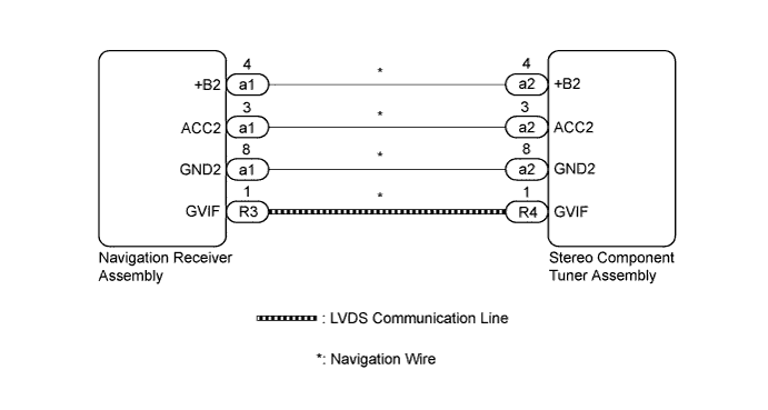
The stereo component tuner assembly and the navigation receiver assembly are connected via LVDS communication line.
This DTC is stored when an LVDS communication error occurs between the stereo component tuner assembly and the navigation receiver assembly.
| DTC No. | DTC Detection Condition | Trouble Area |
|---|---|---|
| B1532 | When any of the following conditions is met:
|
|
Tech Tips
Even if no malfunction is present, this DTC may be stored depending on the battery condition or engine start voltage.
WIRING DIAGRAM
INSPECTION PROCEDURE
Note
After replacing the stereo component tuner assembly of vehicles subscribed to pay-type satellite radio broadcasts, XM radio ID registration is necessary.
PROCEDURE
-
CHECK NAVIGATION WIRE (STEREO COMPONENT TUNER ASSEMBLY POWER SOURCE)
-
Disconnect the a2 stereo component tuner assembly connector.
-
Measure the resistance according to the value(s) in the table below.
Standard Resistance Tester Connection Condition Specified Condition a2-8 (GND2) - Body ground Always Below 1 Ω -
Measure the voltage according to the value(s) in the table below.
Standard Voltage Tester Connection Condition Specified Condition a2-4 (+B2) - a2-8 (GND2) Always 11 to 14 V a2-3 (ACC2) - a2-8 (GND2) Ignition switch ACC 11 to 14 V
NG 
CHECK NAVIGATION WIRE Click here
OK 
-
-
REPLACE NAVIGATION WIRE
-
Replace the navigation wire with a new or known good one Click here.
-
Clear the DTCs Click here.
-
Recheck for DTCs and check that no DTCs are output.
OK No DTCs are output.
NG
REPLACE STEREO COMPONENT TUNER ASSEMBLY Click here
OK 
END
-
-
REPLACE STEREO COMPONENT TUNER ASSEMBLY
-
Replace the stereo component tuner assembly with a new or known good one Click here.
-
Clear the DTCs Click here.
-
Recheck for DTCs and check that no DTCs are output.
OK No DTCs are output.
NG 
REPLACE NAVIGATION RECEIVER ASSEMBLY Click here
OK
END
-
-
CHECK NAVIGATION WIRE
-
Disconnect the a1 navigation receiver assembly connector.
-
Disconnect the a2 stereo component tuner assembly connector.
-
Measure the resistance according to the value(s) in the table below.
Standard Resistance: Tester Connection Condition Specified Condition a1-4 (+B2) - a2-4 (+B2) Always Below 1 Ω a1-3 (ACC2) - a2-3 (ACC2) Always Below 1 Ω a1-8 (GND2) - a2-8 (GND2) Always Below 1 Ω a1-4 (+B2) - Body ground Always 10 kΩ or higher a1-3 (ACC2) - Body ground Always 10 kΩ or higher a1-8 (GND2) - Body ground Always 10 kΩ or higher
NG
REPLACE NAVIGATION WIRE Click here
OK
REPLACE NAVIGATION RECEIVER ASSEMBLY Click here
-