STEERING PAD SWITCH INSPECTION

-
INSPECT STEERING PAD SWITCH ASSEMBLY (w/o TFT Display)
-
Measure the resistance according to the value(s) in the table below.
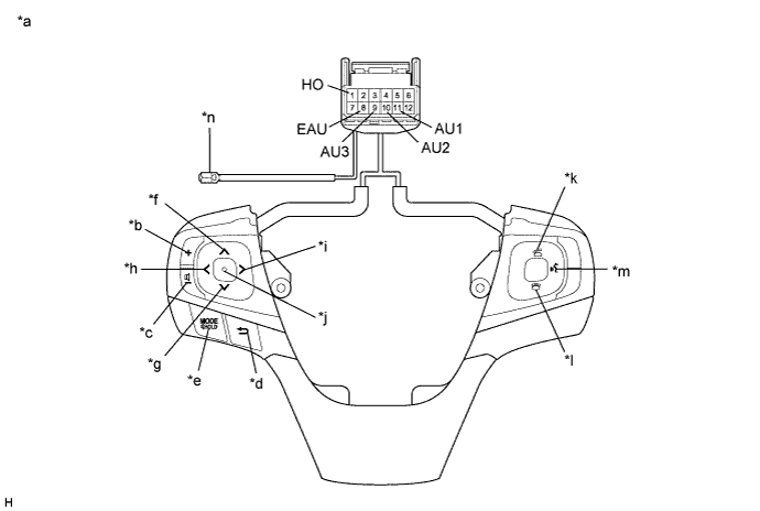
Standard Resistance Tester Connection Condition Specified Condition 1 (HO) - Terminal-A Always Below 2.5 Ω 11 (AU1) - 8 (EAU) No switch pushed 95 to 105 kΩ Up switch pushed Below 2.5 Ω Down switch pushed 313 to 345 Ω Volume+ switch pushed 950 to 1050 Ω Volume- switch pushed 2955 to 3265 Ω 10 (AU2) - 8 (EAU) No switch pushed 95 to 105 kΩ MODE/HOLD switch pushed Below 2.5 Ω On hook switch pushed 313 to 345 Ω Off hook switch pushed 950 to 1050 Ω Voice switch pushed 2955 to 3265 Ω 9 (AU3) - 8 (EAU) No switch pushed 95 to 105 kΩ Enter switch pushed Below 2.5 Ω Back switch pushed 313 to 345 Ω Right switch pushed 950 to 1050 Ω Left switch pushed 2955 to 3265 Ω Tech Tips
If the result is not as specified, replace the steering pad switch assembly.
Text in Illustration *a Component without harness connected
(Steering Pad Switch Assembly)
*b Volume+ *c Volume- *d Back *e MODE/HOLD *f Up *g Down *h Left *i Right *j Enter *k Off hook *l On hook *m Voice *n Terminal-A -
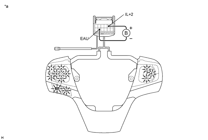
Check the illumination.
-
Connect a battery positive (+) lead to terminal 5 (IL+2) and a negative (-) lead to terminal 8 (EAU) of the steering pad switch assembly connector.
-
Check that the switch illumination comes on.
OK Steering pad switch illumination comes on. Tech Tips
If the result is not as specified, replace the steering pad switch assembly.
Text in Illustration *a Component without harness connected
(Steering Pad Switch Assembly)
- -
-
-
-
INSPECT STEERING PAD SWITCH ASSEMBLY (w/ TFT Display)
-
Measure the resistance according to the value(s) in the table below.
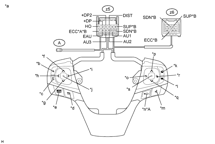
Standard Resistance Tester Connection Condition Specified Condition z5-1 (HO) - A-1 Always Below 2.5 Ω z5-11 (AU1) - z5-8 (EAU) No switch pushed 95 to 105 kΩ Up (LH) switch pushed Below 2.5 Ω Down (LH) switch pushed 313 to 345 Ω Volume+ switch pushed 950 to 1050 Ω Volume- switch pushed 2955 to 3265 Ω z5-10 (AU2) - z5-8 (EAU) No switch pushed 95 to 105 kΩ MODE/HOLD switch pushed Below 2.5 Ω On hook switch pushed 313 to 345 Ω Off hook switch pushed 950 to 1050 Ω Voice switch pushed 2955 to 3265 Ω z5-9 (AU3) - z5-8 (EAU) No switch pushed 95 to 105 kΩ Enter (LH) switch pushed Below 2.5 Ω Back (LH) switch pushed 313 to 345 Ω Right switch pushed 950 to 1050 Ω Left switch pushed 2955 to 3265 Ω z5-3 (+DP2) - z5-8 (EAU) No switch pushed 95 to 105 kΩ Back (RH) switch pushed Below 2.5 Ω Up (RH) switch pushed 313 to 345 Ω Down (RH) switch pushed 950 to 1050 Ω Page switch pushed 2955 to 3265 Ω z5-2 (+DP) - z5-8 (EAU) No switch pushed 95 to 105 kΩ Enter (RH) switch pushed Below 2.5 Ω z5-4 (DIST) - z5-7 (ECC)*1 No switch pushed 1 MΩ or higher Vehicle-to-vehicle distance control switch pushed Below 2.5 Ω z5-6 (SUP) - z6-2 (SUP)*2 Always Below 2.5 Ω z5-7 (ECC) - z6-7 (ECC)*2 Always Below 2.5 Ω z5-12 (SDN) - z6-3 (SDN)*2 Always Below 2.5 Ω
-
*1: w/ Vehicle-to-vehicle Distance Control Switch
-
*2: w/ Shift Paddle Switch
Tech Tips
If the result is not as specified, replace the steering pad switch assembly.
Text in Illustration *A w/ Vehicle-to-vehicle Distance Control Switch *B w/ Shift Paddle Switch *a Component without harness connected
(Steering Pad Switch Assembly)
*b Volume+ *c Volume- *d Back (LH) *e MODE/HOLD *f Up (LH) *g Down (LH) *h Left *i Right *j Enter (LH) *k Off hook *l On hook *m Voice *n Vehicle-to-vehicle distance control *o Back (RH) *p Up (RH) *q Down (RH) *r Page *s Enter (RH) - - -
-
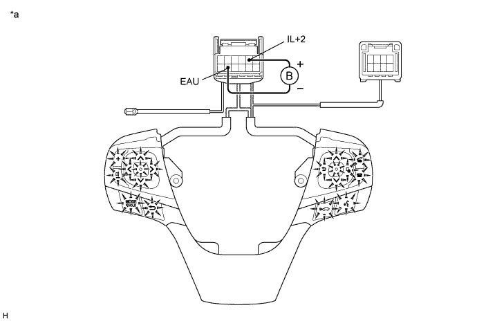
Check the illumination.
-
Connect a battery positive (+) lead to terminal 5 (IL+2) and a negative (-) lead to terminal 8 (EAU) of the steering pad switch assembly connector.
-
Check that the switch illumination comes on.
OK Steering pad switch illumination comes on. Tech Tips
If the result is not as specified, replace the steering pad switch assembly.
Text in Illustration *a Component without harness connected
(Steering Pad Switch Assembly)
- -
-
-