REAR SUSPENSION MEMBER INSTALLATION

-
INSTALL HOLE PLUG
-
Install the 4 hole plugs to the rear suspension member sub-assembly.
-
-
INSTALL REAR SUSPENSION MEMBER BODY MOUNTING FRONT CUSHION LH
-
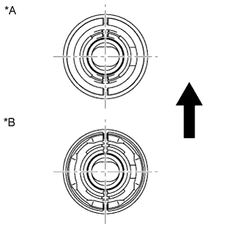
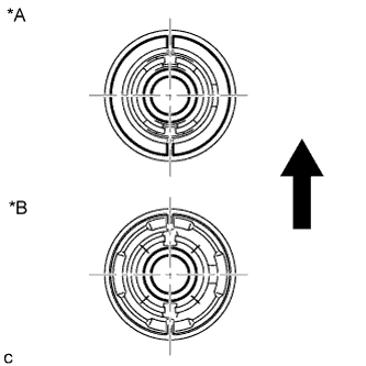
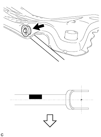
Text in Illustration *A Type A: *B Type B: 
Front of the Vehicle Temporarily install a new rear suspension member body mounting front cushion LH to the position shown in the illustration.
-
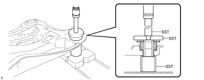
Using SST and a press, install the rear suspension member body mounting front cushion LH to the rear suspension member sub-assembly.
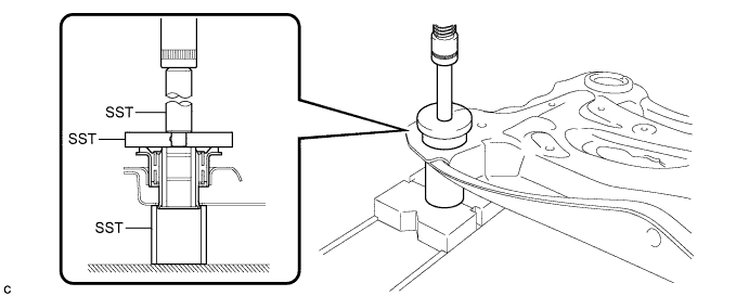
- SST
- 09710-30012 ( 09710-04061 )
- 09950-60010 ( 09951-00650 )
- 09950-70010 ( 09951-07100 )
Tech Tips
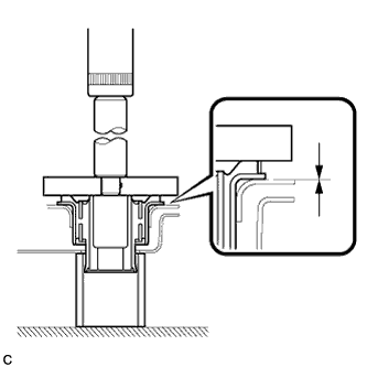
Slowly press in the rear suspension member body mounting front cushion LH.
-
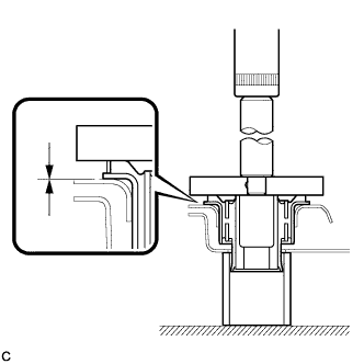
While observing from the side, press in the rear suspension member body mounting front cushion LH until there is no clearance between the rear suspension member body mounting front cushion LH and the rear suspension member sub-assembly as shown in the illustration.
Note
Do not press the rear suspension member excessively, or it will easily deform.
-
-
INSTALL REAR SUSPENSION MEMBER BODY MOUNTING FRONT CUSHION RH
-
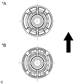
Text in Illustration *A Type A: *B Type B: Front of the Vehicle Temporarily install a new rear suspension member body mounting front cushion RH to the position shown in the illustration.
-
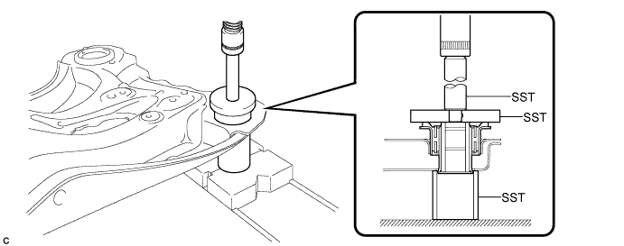
Using SST and a press, install the rear suspension member body mounting front cushion RH to the rear suspension member sub-assembly.
- SST
- 09710-30012 ( 09710-04061 )
- 09950-60010 ( 09951-00650 )
- 09950-70010 ( 09951-07100 )
Tech Tips
Slowly press in the rear suspension member body mounting front cushion RH.
-

While observing from the side, press in the rear suspension member body mounting front cushion RH until there is no clearance between the rear suspension member body mounting front cushion RH and the rear suspension member sub-assembly as shown in the illustration.
Note
Do not press the rear suspension member excessively, or it will easily deform.
-
-
INSTALL REAR SUSPENSION MEMBER BODY MOUNTING REAR CUSHION (for LH Side)
-
Text in Illustration *A Type A: *B Type B: Front of the Vehicle Temporarily install a new rear suspension member body mounting rear cushion (LH side) to the position shown in the illustration.
-
Using SST and a press, install the rear suspension member body mounting rear cushion (LH side) to the rear suspension member sub-assembly.
- SST
- 09710-30012 ( 09710-04061 )
- 09950-60010 ( 09951-00650 )
- 09950-70010 ( 09951-07100 )
Tech Tips
Slowly press in the rear suspension member body mounting rear cushion.
-
While observing from the side, press in the rear suspension member body mounting rear cushion (LH side) until there is no clearance between the rear suspension member body mounting rear cushion (LH side) and the rear suspension member sub-assembly as shown in the illustration.
Note
Do not press the rear suspension member excessively, or it will easily deform.
-
-
INSTALL REAR SUSPENSION MEMBER BODY MOUNTING REAR CUSHION (for RH Side)
Tech Tips
Perform the same procedure as the LH side.
-
INSTALL REAR NO. 1 SUSPENSION ARM ASSEMBLY LH
-
Temporarily tighten the rear No. 1 suspension arm assembly (inner side) with the bolt.
Text in Illustration Bolt 
Front of the Vehicle 
Paint Mark Tech Tips
Ensure that the paint mark faces the rear of the vehicle.
-
Set the rear No.1 suspension arm assembly in the position shown in the illustration, and fully tighten the bolt.
- Torque:
- 100 N*m { 1020 kgf*cm, 74 ft.*lbf }
-
-
INSTALL REAR NO. 1 SUSPENSION ARM ASSEMBLY RH
Tech Tips
Perform the same procedure as the LH side.
-
TEMPORARILY INSTALL REAR NO. 2 SUSPENSION ARM ASSEMBLY LH
-
Temporarily tighten the rear No. 2 suspension arm assembly (inside) with the bolt.
Text in Illustration Bolt Paint Mark Tech Tips
Ensure that the paint mark faces the rear of the vehicle.
-
-
TEMPORARILY INSTALL REAR NO. 2 SUSPENSION ARM ASSEMBLY RH
Tech Tips
Perform the same procedure as the LH side.
-
INSTALL REAR SUSPENSION MEMBER SUB-ASSEMBLY
-
w/ Member Cushion:
-
Install 2 new differential support member cushions and 2 new differential support member upper stoppers to the rear suspension member sub-assembly.
-
-
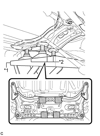
Text in Illustration *1 Engine Lifter *2 Attachment 
Attachment Placement Location Support the rear suspension member sub-assembly with an engine lifter using 4 attachments or equivalent tools.
Note
-
Make sure to secure the rear suspension member sub-assembly to prevent it from dropping.
-
Use the attachments to keep the rear suspension member sub-assembly level.
-
-
Raise the rear suspension member sub-assembly until there is no clearance between the rear suspension member sub-assembly and the vehicle body.
Note
When raising the rear suspension member sub-assembly, be careful not to damage the vehicle body or other components installed on the vehicle.
-
Install the rear suspension member sub-assembly, rear suspension member lower stopper sub-assembly LH and rear suspension member lower stopper sub-assembly RH with the 4 nuts.
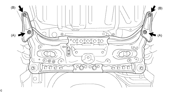
- Torque:
- Nut A
- 55 N*m { 561 kgf*cm, 41 ft.*lbf }
- Nut B
- 38 N*m { 387 kgf*cm, 28 ft.*lbf }
-
Install the rear suspension member sub-assembly and 2 rear suspension member lower stoppers with the 2 bolts.
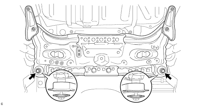
- Torque:
- 55 N*m { 561 kgf*cm, 41 ft.*lbf }
Note
Be sure to install the rear suspension member sub-assembly with the rear suspension member lower stoppers in the correct direction, as shown in the illustration.
-
-
INSTALL NO. 3 EXHAUST PIPE SUPPORT BRACKET
-
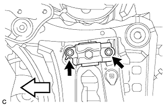
Install the No. 3 exhaust pipe support bracket to the rear suspension member sub-assembly with the 2 bolts.
- Torque:
- 33 N*m { 337 kgf*cm, 24 ft.*lbf }
-
-
INSTALL JACK UP BRACKET (for 2GR-FE)
-
Install the jack up bracket to the rear suspension member sub-assembly with the 2 bolts.
- Torque:
- 39 N*m { 398 kgf*cm, 29 ft.*lbf }
-
-
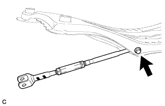
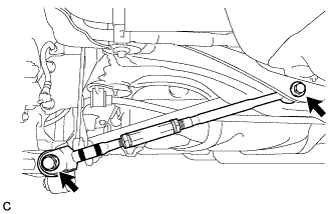
INSTALL REAR SUSPENSION MEMBER DAMPER (w/ Dynamic Damper)
-
Install the rear suspension member damper to the rear suspension member sub-assembly with the 2 bolts.
Text in Illustration Front of the Vehicle - Torque:
- 29 N*m { 296 kgf*cm, 21 ft.*lbf }
-
-
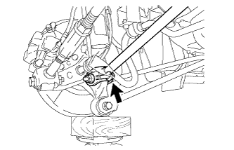
CONNECT REAR NO. 1 SUSPENSION ARM ASSEMBLY LH
-
Connect the rear No. 1 suspension arm assembly (outer side) to the rear axle carrier sub-assembly with the bolt and nut.
Note
When temporarily tightening the bolt, keep the nut from rotating.
Tech Tips
Insert the bolt from the front of the vehicle.
-
-
CONNECT REAR NO. 1 SUSPENSION ARM ASSEMBLY RH
Tech Tips
Perform the same procedure as the LH side.
-
CONNECT REAR NO. 2 SUSPENSION ARM ASSEMBLY LH
-
Connect the rear No. 2 suspension arm assembly (outer side) to the rear axle carrier sub-assembly with the bolt and nut.
Note
When temporarily tightening the bolt, keep the nut from rotating.
Tech Tips
Insert the bolt from the rear of the vehicle.
-
-
CONNECT REAR NO. 2 SUSPENSION ARM ASSEMBLY RH
Tech Tips
Perform the same procedure as the LH side.
-
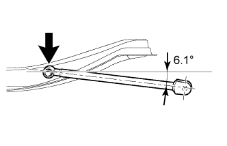
STABILIZE SUSPENSION
-
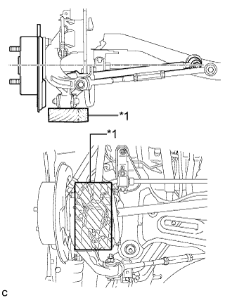
Text in Illustration *1 Wooden Block Jack up the rear axle carrier sub-assembly, placing a wooden block under it to avoid damage. Apply load to the suspension so that the installed bolt of the rear No. 1 suspension arm assembly (inner side) is horizontally aligned with the center of the rear axle hub.
CAUTION:
Do not jack up the rear axle carrier sub-assembly too high as the vehicle may fall.
Note
-
When jacking up the rear axle carrier sub-assembly, be sure to jack it up slowly.
-
Make sure to perform this operation with the vehicle kept as low as possible.
-
-
-
FULLY TIGHTEN REAR NO. 1 SUSPENSION ARM ASSEMBLY LH
-
Fully tighten the bolt.
- Torque:
- 100 N*m { 1020 kgf*cm, 74 ft.*lbf }
Note
Since a stopper nut is used, fully tighten the bolt.
-
-
FULLY TIGHTEN REAR NO. 1 SUSPENSION ARM ASSEMBLY RH
Tech Tips
Perform the same procedure as the LH side.
-
FULLY TIGHTEN REAR NO. 2 SUSPENSION ARM ASSEMBLY LH
-
Fully tighten the 2 bolts.
- Torque:
- 100 N*m { 1020 kgf*cm, 74 ft.*lbf }
-
-
FULLY TIGHTEN REAR NO. 2 SUSPENSION ARM ASSEMBLY RH
Tech Tips
Perform the same procedure as the LH side.
-
INSTALL REAR HEIGHT CONTROL SENSOR SUB-ASSEMBLY (w/ Height Control Sensor)
-
INSTALL REAR STABILIZER BAR
-
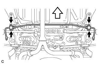
Install the rear stabilizer bar with the 4 nuts.
Text in Illustration Nut Front of the Vehicle - Torque:
- 31 N*m { 316 kgf*cm, 23 ft.*lbf }
-
-
CONNECT REAR STABILIZER LINK ASSEMBLY LH
-
Connect the rear stabilizer link assembly LH to the rear stabilizer bar with nut.
- Torque:
- 39 N*m { 400 kgf*cm, 29 ft.*lbf }
If the ball joint turns together with the nut, use a hexagon wrench to hold the stud.
-
-
CONNECT REAR STABILIZER LINK ASSEMBLY RH
Tech Tips
Perform the same procedure as the LH side.
-
INSTALL CENTER EXHAUST PIPE ASSEMBLY
-
for 2GR-FE: Click here
-
for 2AR-FE: Click here
-
-
INSTALL NO. 2 FLOOR UNDER COVER (w/ Floor Under Cover)
-
Install the No. 2 floor under cover with the 2 bolts, 3 nuts, screw and 2 clips.
- Torque:
- Bolt
- 12 N*m { 122 kgf*cm, 9 ft.*lbf }
- Nut
- 4.0 N*m { 41 kgf*cm, 35 in.*lbf }
-
-
INSTALL NO. 1 FLOOR UNDER COVER
-
Install the No. 1 floor under cover with the 2 bolts, 3 nuts, screw and 2 clips.
- Torque:
- Bolt
- 12 N*m { 122 kgf*cm, 9 ft.*lbf }
- Nut
- 4.0 N*m { 41 kgf*cm, 35 in.*lbf }
-
-
INSTALL REAR WHEELS
- Torque:
- 103 N*m { 1049 kgf*cm, 76 ft.*lbf }
-
INSPECT AND ADJUST REAR WHEEL ALIGNMENT
-
HEIGHT CONTROL SENSOR SIGNAL INITIALIZE (w/ Height Control Sensor)
-
ADJUST HEADLIGHT AIMING (w/ Height Control Sensor)