FRONT SUSPENSION MEMBER (When Using the Engine Support Bridge for 2AR-FE) INSTALLATION

-
INSTALL HOLE PLUG
-
Install each hole plug to the front frame assembly.
-
-
INSTALL FRONT SUSPENSION MEMBER BODY MOUNTING REAR CUSHION LH
-

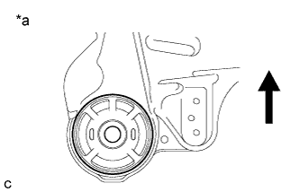
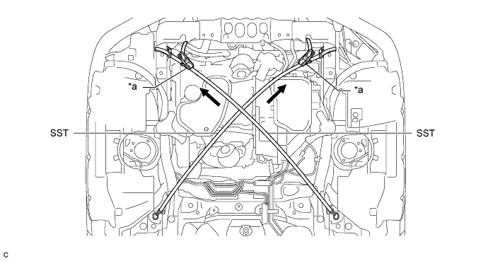
Text in Illustration *a View from Underneath 
Front of the Vehicle Temporarily install a new front suspension member body mounting rear cushion LH while confirming the installation direction.
Note
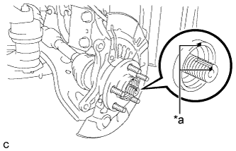
Position the front suspension member body mounting rear cushion LH in the correct direction.
-
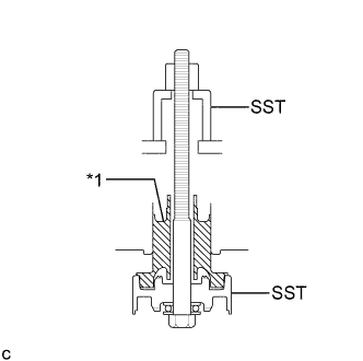
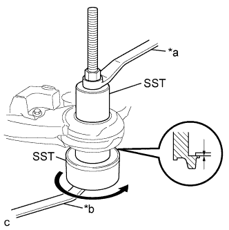
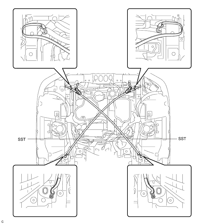
Text in Illustration *1 Front Suspension Member Body Mounting Rear Cushion LH Install SST as shown in the illustration.
- SST
- 09830-10010 ( 09830-01010, 09830-01020, 09830-01030, 09830-01060 )
-
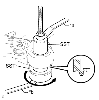
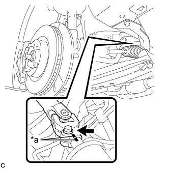
Text in Illustration *a Hold *b Turn Using SST, install the front suspension member body mounting rear cushion LH as shown in the illustration.
Note
Check that there is no clearance between the front frame assembly and the front suspension member body mounting rear cushion LH.
-
-
INSTALL FRONT SUSPENSION MEMBER BODY MOUNTING REAR CUSHION RH
-
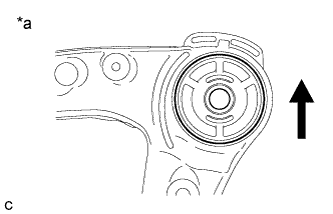
Text in Illustration *a View from Underneath Front of the Vehicle Temporarily install a new front suspension member body mounting rear cushion RH while confirming the installation direction.
Note
Position the front suspension member body mounting rear cushion RH in the correct direction.
-
Install SST using the same procedure as the front suspension member body mounting rear cushion LH.
- SST
- 09830-10010 ( 09830-01010, 09830-01020, 09830-01030, 09830-01060 )
-
Using SST, install the front suspension member body mounting rear cushion RH.
- SST
- 09830-10010 ( 09830-01010, 09830-01020, 09830-01030, 09830-01060 )
Tech Tips
Perform the same procedure as for the LH side.
-
-
INSTALL FRONT SUSPENSION MEMBER BODY MOUNTING FRONT CUSHION
-
Text in Illustration *a View from Underneath Front of the Vehicle Temporarily install a new front suspension member body mounting front cushion while confirming the installation direction.
Note
Position the front suspension member body mounting front cushion in the correct direction.
-
Install SST using the same procedure as the front suspension member body mounting rear cushion LH.
- SST
- 09830-10010 ( 09830-01010, 09830-01020, 09830-01030, 09830-01060 )
-
Text in Illustration *a Hold *b Turn Using SST, install the front suspension member body mounting front cushion as shown in the illustration.
- SST
- 09830-10010 ( 09830-01010, 09830-01020, 09830-01030, 09830-01060 )
Note
Check that there is no clearance between the front frame assembly and the front suspension member body mounting front cushion.
-
-
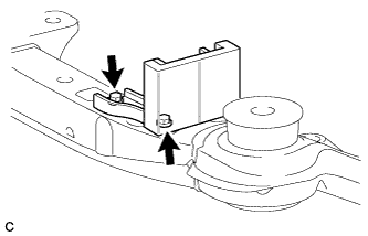
INSTALL FRONT SUSPENSION MEMBER BODY MOUNTING REAR STOPPER
-
Install the 2 front suspension member body mounting rear stoppers to the front frame assembly.
-
-
INSTALL FRONT SUSPENSION MEMBER BODY MOUNTING FRONT STOPPER
-
Install the 2 front suspension member body mounting front stoppers to the front frame assembly.
-
-
INSTALL FRONT SUSPENSION MEMBER DYNAMIC DAMPER
-
Install the front suspension member dynamic damper to the front frame assembly with the 2 bolts.
- Torque:
- 29 N*m { 296 kgf*cm, 21 ft.*lbf }
-
-
INSTALL FRONT LOWER NO. 1 SUSPENSION ARM SUB-ASSEMBLY LH
-
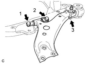
Install the front lower No. 1 suspension arm sub-assembly LH to the front frame assembly with the 3 bolts and nut in the order shown in the illustration.
- Torque:
- Bolt 1, 2
- 200 N*m { 2039 kgf*cm, 148 ft.*lbf }
- Bolt 3
- 135 N*m { 1377 kgf*cm, 100 ft.*lbf }
Note
While keeping the nut from rotating, tighten the bolt.
-
-
INSTALL FRONT LOWER NO. 1 SUSPENSION ARM SUB-ASSEMBLY RH
Tech Tips
Perform the same procedure as for the LH side.
-
INSTALL STEERING LINK ASSEMBLY
-
Install the steering link assembly with the 2 bolts and 2 nuts.
- Torque:
- 70 N*m { 714 kgf*cm, 52 ft.*lbf }
Note
-
Keep the nut from rotating while turning the bolt because the nut has its own stopper.
-
Make sure to tighten the bolts starting from the pinion shaft side.
-
-
INSTALL FRONT STABILIZER BAR WITH FRONT STABILIZER LINK ASSEMBLY
-
Install the front stabilizer bar with 2 front stabilizer link assemblies to the front frame assembly.
-
-
INSTALL FRONT NO. 1 STABILIZER BRACKET LH
-
Install the front No. 1 stabilizer bracket LH to the front frame assembly with the 2 bolts.
- Torque:
- 27 N*m { 275 kgf*cm, 20 ft.*lbf }
-
-
INSTALL FRONT NO. 1 STABILIZER BRACKET RH
Tech Tips
Perform the same procedure as for the LH side.
-
INSTALL FRONT FRAME ASSEMBLY
-
Slowly jack up the front frame assembly with an engine lifter using 4 attachments or equivalent tools.
CAUTION:
-
The front frame assembly is a heavy component. Make sure that it is supported securely.
-
Make sure to secure the front frame assembly to prevent it from dropping.
Note
Use the attachments to keep the front frame assembly level.
-
-
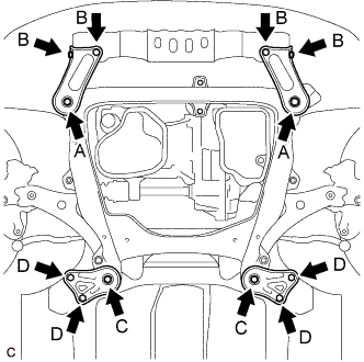
Install the frame side rail plates RH and LH with the 4 bolts and 2 nuts.
- Torque:
- A
- 85 N*m { 867 kgf*cm, 63 ft.*lbf }
- B
- 32 N*m { 329 kgf*cm, 24 ft.*lbf }
-
Install the front suspension member rear braces RH and LH with the 4 bolts and 2 nuts.
- Torque:
- C
- 85 N*m { 867 kgf*cm, 63 ft.*lbf }
- D
- 32 N*m { 329 kgf*cm, 24 ft.*lbf }
-
-
REMOVE BELT
-
Install SST to the vehicle body as shown in the illustration.
- SST
- 09727-00110
-
Using the SST ratchet buckle, tighten the SST belt until there is no slack.
Text in Illustration *a Ratchet Buckle - -
-
-
REMOVE ENGINE SUPPORT BRIDGE
-
Remove SST from the vehicle body.
Note
Prevent SST from contacting the vehicle body or windshield.
-
Install the 2 hood support assemblies.
-
-
REMOVE ENGINE HANGERS
-
Remove the 2 bolts and No. 1 and No. 2 engine hangers from the engine assembly.
-
-
INSTALL NO. 2 ENGINE MOUNTING STAY RH
-
Install the No. 2 engine mounting stay RH with the 2 bolts.
- Torque:
- 38 N*m { 387 kgf*cm, 28 ft.*lbf }
-
-
INSTALL FRONT ENGINE MOUNTING INSULATOR
-
Install the front engine mounting insulator to the front frame assembly with the 3 nuts.
- Torque:
- 58 N*m { 591 kgf*cm, 43 ft.*lbf }
-
-
INSTALL ENGINE MOUNTING INSULATOR LH
-
Install the engine mounting insulator LH to the front frame assembly with the 3 nuts.
- Torque:
- 99 N*m { 1010 kgf*cm, 73 ft.*lbf }
-
Install the 2 hole plugs.
-
-
INSTALL ENGINE MOUNTING INSULATOR RH
-
Install the engine mounting insulator RH to the front frame assembly with the 3 nuts.
- Torque:
- 99 N*m { 1010 kgf*cm, 73 ft.*lbf }
-
Install the 2 hole plugs.
-
-
CONNECT STEERING INTERMEDIATE SHAFT ASSEMBLY
-
Text in Illustration *a Matchmark Align the matchmarks and install the steering intermediate shaft to the steering link assembly.
-
Install the bolt.
- Torque:
- 35 N*m { 360 kgf*cm, 26 ft.*lbf }
-
-
INSTALL FRONT DRIVE SHAFT ASSEMBLY LH
-
Text in Illustration *a Matchmark Align the matchmarks and install the front drive shaft assembly to the front axle hub sub-assembly.
Note
Be careful not to damage the drive shaft boot or speed sensor rotor.
-
-
INSTALL FRONT DRIVE SHAFT ASSEMBLY RH
Tech Tips
Perform the same procedure as for the LH side.
-
CONNECT FRONT LOWER NO. 1 SUSPENSION ARM SUB-ASSEMBLY LH
-
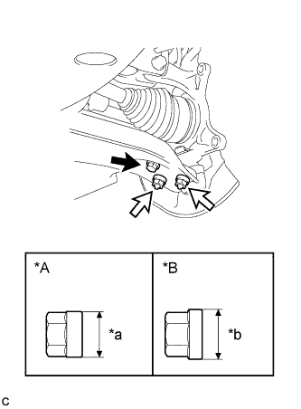
Text in Illustration *A Type A Nut *B Type B Nut *a 20 mm (0.787 in.) *b 22 mm (0.866 in.) Bolt 
Nut Connect the front lower No. 1 suspension arm sub-assembly to the front lower ball joint assembly with the bolt and 2 nuts.
- Torque:
- Type A Nut and Bolt
- 75 N*m { 765 kgf*cm, 55 ft.*lbf }
- Type B Nut and Bolt
- 92 N*m { 938 kgf*cm, 68 ft.*lbf }
Note
-
The tightening torque for the bolt differs depending on the type of nut.
-
Make sure to tighten the bolt to the same torque as the nuts.
-
-
CONNECT FRONT LOWER NO. 1 SUSPENSION ARM SUB-ASSEMBLY RH
Tech Tips
Perform the same procedure as for the LH side.
-
CONNECT TIE ROD ASSEMBLY LH
-
Connect the tie rod assembly LH to the steering knuckle with the nut.
- Torque:
- 49 N*m { 500 kgf*cm, 36 ft.*lbf }
-
Install a new cotter pin.
Note
Further tighten the nut up to 60° if the holes for the cotter pin are not aligned.
-
-
CONNECT TIE ROD ASSEMBLY RH
Tech Tips
Perform the same procedure as for the LH side.
-
INSTALL FRONT STABILIZER LINK ASSEMBLY LH
-
Install the front stabilizer link assembly to the front shock absorber assembly with the nut.
- Torque:
- 125 N*m { 1275 kgf*cm, 92 ft.*lbf }
If the ball joint turns together with the nut, use a wrench to hold the stud bolt.
-
-
INSTALL FRONT STABILIZER LINK ASSEMBLY RH
Tech Tips
Perform the same procedure as for the LH side.
-
INSTALL FRONT AXLE SHAFT NUT LH
-
Clean the threaded parts on the front drive shaft assembly and a new axle shaft nut using a non-residue solvent.
Note
-
Be sure to perform this work even when using a new drive shaft.
-
Keep the threaded parts free of oil and foreign matter.
-
-
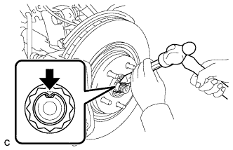
Using a socket wrench (30 mm), install the front axle shaft nut.
- Torque:
- 294 N*m { 2998 kgf*cm, 217 ft.*lbf }
-
Using a chisel and hammer, stake the front axle shaft nut.
-
-
INSTALL FRONT AXLE SHAFT NUT RH
Tech Tips
Perform the same procedure as for the LH side.
-
INSTALL FRONT EXHAUST PIPE ASSEMBLY
-
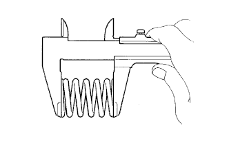
Using a vernier caliper, measure the free length of the compression spring.
Minimum Free Length 40.5 mm (1.60 in.) Tech Tips
If the length is less than the minimum, replace the compression spring.
-
Temporarily install a new gasket to the exhaust manifold converter sub-assembly.
-
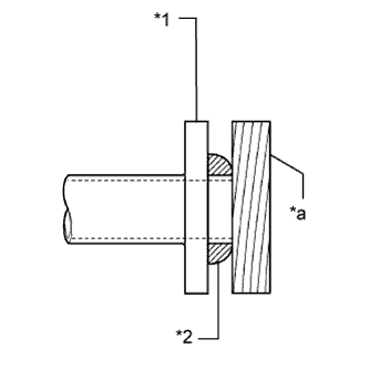
Text in Illustration *1 Exhaust Manifold Converter Sub-assembly *2 Gasket *a Wooden Block Using a plastic hammer and wooden block, tap in the gasket until its surface is flush with the exhaust manifold converter sub-assembly.
Note
-
Be sure to install the gasket in the correct direction.
-
Do not reuse the gasket.
-
Do not damage the gasket.
-
Do not push in the gasket by using the exhaust pipe when connecting it.
-
-
Install a new gasket to the front exhaust pipe assembly.
-
Connect the front exhaust pipe assembly to the exhaust pipe support.
-
Install the front exhaust pipe assembly with the 2 compression springs, 2 bolts and 2 nuts.
- Torque:
- 43 N*m { 438 kgf*cm, 32 ft.*lbf }
-
Connect the heated oxygen sensor connector.
-
-
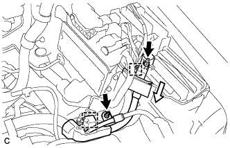
INSTALL NO. 1 AIR CLEANER BRACKET
-
Install the No. 1 air cleaner bracket with the bolt.
- Torque:
- 8.0 N*m { 82 kgf*cm, 71 in.*lbf }
-
Connect the 2 wire clamps.
-
-
CONNECT ENGINE WIRE
-
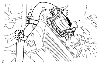
Connect the 2 wire clamps.
-
Connect the ECM connector with the lock lever.
-
Connect the engine wire to the engine room relay block.
-
Connect the 4 connectors.
-
Connect the engine wire to the engine room relay block with the clamp.
-
Connect the wire clamp and install the 2 nuts.
- Torque:
- 8.0 N*m { 82 kgf*cm, 71 in.*lbf }
-
Install the No. 1 relay block cover.
-
-
INSTALL BATTERY
-
Install the battery and battery tray.
-
Install the battery clamp with the bolt and nut.
- Torque:
- Bolt
- 9.0 N*m { 92 kgf*cm, 80 in.*lbf }
- Nut
- 3.5 N*m { 36 kgf*cm, 31 in.*lbf }
-
Connect the cable to the positive (+) battery terminal with the nut.
- Torque:
- 6.9 N*m { 70 kgf*cm, 61 in.*lbf }
-
-
INSTALL AIR CLEANER CASE SUB-ASSEMBLY
-
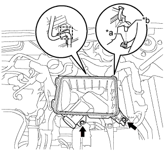
Text in Illustration *a Hole *b Projection Insert the projection of the air cleaner case sub-assembly to the hole of the No. 2 air cleaner bracket as shown in the illustration.
-
Tighten the 2 bolts.
- Torque:
- 5.0 N*m { 51 kgf*cm, 44 in.*lbf }
-
Connect the wire harness clamp.
-
-
INSTALL AIR CLEANER FILTER ELEMENT SUB-ASSEMBLY
-
Install the air cleaner filter element sub-assembly.
Note
Install the air cleaner filter element sub-assembly with the printed side facing the vehicle front.
-
-
INSTALL AIR CLEANER CAP SUB-ASSEMBLY
-
Install the air cleaner cap sub-assembly with the 2 clamps.
-
Install the air cleaner hose with the hose clamp.
-
Connect the ventilation hose to the cylinder head cover.
-
Install the fuel vapor feed hose to the air cleaner hose.
-
Connect the mass air flow meter connector and 2 wire harness clamps to the air cleaner cap sub-assembly.
-
Connect the vacuum switching valve assembly to the air cleaner hose.
-
-
INSTALL INLET AIR CLEANER ASSEMBLY
-
Install the inlet air cleaner assembly with the 2 bolts.
- Torque:
- 8.0 N*m { 82 kgf*cm, 71 in.*lbf }
-
-
CONNECT CABLE TO NEGATIVE BATTERY TERMINAL
-
Connect the negative (-) cable to the negative (-) battery terminal.
- Torque:
- 6.9 N*m { 70 kgf*cm, 61 in.*lbf }
Note
When disconnecting the cable, some systems need to be initialized after the cable is reconnected Click here.
-
-
INSPECT FOR EXHAUST GAS LEAK
-
INSTALL NO. 1 ENGINE COVER SUB-ASSEMBLY
-
Fit the 3 pins and install the No. 1 engine cover sub-assembly.
-
-
INSTALL COOL AIR INTAKE DUCT SEAL
-
Install the cool air intake duct seal with the 9 clips.
-
-
INSTALL FRONT FENDER APRON SEAL LH
-
INSTALL FRONT FENDER APRON SEAL RH
-
INSTALL ENGINE UNDER COVER LH
-
INSTALL FRONT WHEEL OPENING EXTENSION PAD LH
-
INSTALL ENGINE UNDER COVER RH
-
INSTALL FRONT WHEEL OPENING EXTENSION PAD RH
-
INSTALL FRONT WHEEL
- Torque:
- 103 N*m { 1049 kgf*cm, 76 ft.*lbf }
-
INSPECT AND ADJUST FRONT WHEEL ALIGNMENT
-
CHECK FOR SPEED SENSOR SIGNAL