FRONT SUSPENSION MEMBER (When Using the Engine Support Bridge for 2AR-FE) REMOVAL

-
PRECAUTION
Note
After turning the ignition switch off, waiting time may be required before disconnecting the cable from the negative (-) battery terminal. Therefore, make sure to read the disconnecting the cable from the negative (-) battery terminal notices before proceeding with work Click here.
-
ALIGN FRONT WHEELS FACING STRAIGHT AHEAD
-
SECURE STEERING WHEEL
-
DISCONNECT CABLE FROM NEGATIVE BATTERY TERMINAL
Note
When disconnecting the cable, some systems need to be initialized after the cable is reconnected Click here.
-
REMOVE FRONT WHEELS
-
REMOVE FRONT WHEEL OPENING EXTENSION PAD LH
-
REMOVE ENGINE UNDER COVER LH
-
REMOVE FRONT WHEEL OPENING EXTENSION PAD RH
-
REMOVE ENGINE UNDER COVER RH
-
REMOVE FRONT FENDER APRON SEAL LH
-
REMOVE FRONT FENDER APRON SEAL RH
-
REMOVE COOL AIR INTAKE DUCT SEAL
-
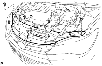
Remove the 9 clips and cool air intake duct seal.
-
-
REMOVE NO. 1 ENGINE COVER SUB-ASSEMBLY
-
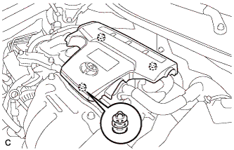
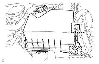
Lift the rear of the No. 1 engine cover sub-assembly to detach the No. 1 engine cover sub-assembly from the 2 pins, and then lift the front of the No. 1 engine cover sub-assembly to detach the No. 1 engine cover sub-assembly from the pin and remove the No. 1 engine cover sub-assembly.
Note
Attempting to disengage both front and rear pins at the same time may cause the No. 1 engine cover sub-assembly to break.
-
-
REMOVE INLET AIR CLEANER ASSEMBLY
-
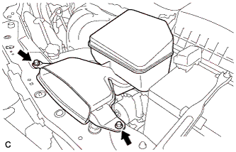
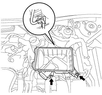
Remove the 2 bolts and inlet air cleaner assembly.
-
-
REMOVE AIR CLEANER CAP SUB-ASSEMBLY
-
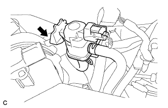
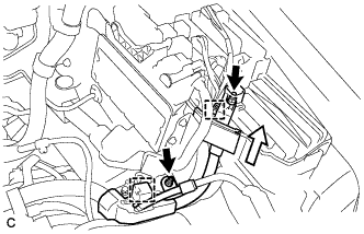
Disconnect the vacuum switching valve assembly from the air cleaner hose.
-
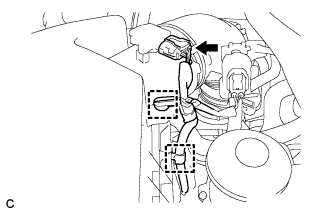
Disconnect the mass air flow meter connector and 2 wire harness clamps from the air cleaner cap sub-assembly.
-
Separate the fuel vapor feed hose from the air cleaner hose.
-
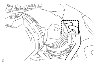
Disconnect the ventilation hose from the cylinder head cover.
-
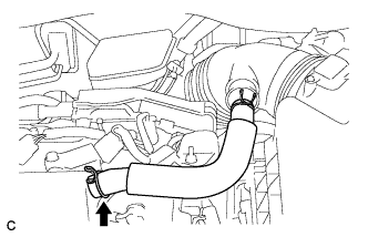
Loosen the hose clamp and disconnect the air cleaner hose from the throttle with motor body assembly.
-
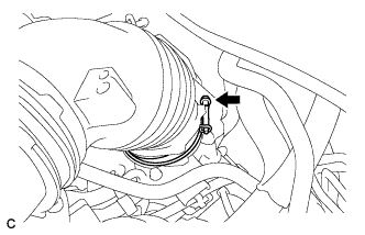
Release the 2 clamps and remove the air cleaner cap sub-assembly.
-
-
REMOVE AIR CLEANER FILTER ELEMENT SUB-ASSEMBLY
-
Remove the air cleaner filter element sub-assembly.
-
-
REMOVE AIR CLEANER CASE SUB-ASSEMBLY
-
Disconnect the wire harness clamp.
-
Remove the 2 bolts and air cleaner case sub-assembly.
-
-
REMOVE BATTERY
-
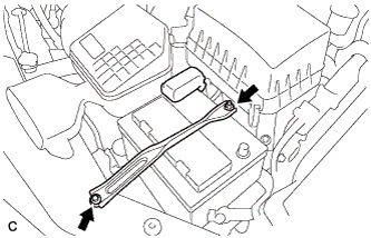
Loosen the nut, and separate the positive (+) battery terminal.
-
Loosen the nut, and remove the bolt and battery clamp.
-
Remove the battery and battery tray.
-
-
DISCONNECT ENGINE WIRE
-
Remove the No. 1 relay block cover.
-
Remove the 2 nuts and disconnect the wire clamp.
-
Using a screwdriver, unlock the clamp and separate the engine wire from the engine room relay block.
-
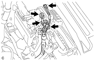
Disconnect the 4 connectors.
-
Using a screwdriver, unlock the clamp and separate the engine wire from the engine room relay block.
-
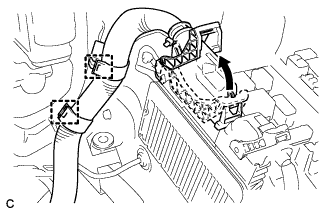
Pull up the lever to disconnect the ECM connector.
-
Disconnect the 2 wire clamps.
-
-
DISCONNECT NO. 1 AIR CLEANER BRACKET
-
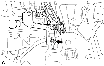
Disconnect the 2 wire clamps.
-
Remove the bolt and No. 1 air cleaner bracket.
-
-
REMOVE FRONT EXHAUST PIPE ASSEMBLY
-
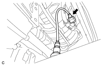
Disconnect the heated oxygen sensor connector.
-
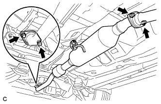
Remove the 2 bolts, 2 compression springs, 2 nuts and front exhaust pipe assembly.
-
Disconnect the front exhaust pipe assembly from the exhaust pipe support.
-
Remove the 2 gaskets from the exhaust manifold converter sub-assembly and front exhaust pipe assembly.
-
-
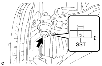
REMOVE FRONT AXLE SHAFT NUT LH
-
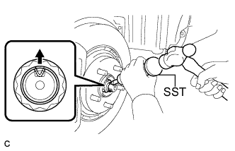
Using SST and a hammer, release the staked part of the front axle shaft nut.
- SST
- 09930-00010
Note
Loosen the staked part of the nut completely, otherwise the threads of the drive shaft may be damaged.
-
While applying the brakes, remove the front axle shaft nut.
-
-
REMOVE FRONT AXLE SHAFT NUT RH
Tech Tips
Perform the same procedure as for the LH side
-
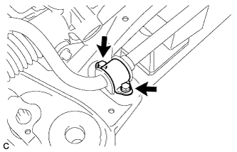
SEPARATE FRONT STABILIZER LINK ASSEMBLY LH
-
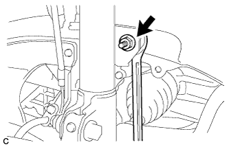
Remove the nut and separate the front stabilizer link assembly from the front shock absorber assembly.
If the ball joint turns together with the nut, use a wrench to hold the stud bolt.
-
-
SEPARATE FRONT STABILIZER LINK ASSEMBLY RH
Tech Tips
Perform the same procedure as for the LH side
-
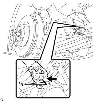
SEPARATE TIE ROD ASSEMBLY LH
-
Remove the cotter pin and nut.
-
Install SST to the tie rod assembly LH.
- SST
- 09960-20010 ( 09961-02060 )
Note
Make sure that the lower ends of the tie rod assembly LH and SST are aligned.
-
Secure SST using a string.
Note
Be sure to tighten the string firmly to secure SST to the steering knuckle to prevent SST from falling off.
-
Using SST, separate the tie rod assembly LH from the steering knuckle.
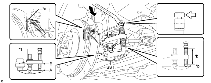
Text in Illustration *1 Center Nut - - *a String *b Grease Application Area 
Place the wrench here. - - - SST
- 09960-20010 ( 09961-02010 )
CAUTION:
Apply grease to the bolt threads and the tip of SST.
Note
-
Install SST with the center nut so that A and B shown in the illustration are parallel. Otherwise, the dust cover may be damaged.
-
Be sure to place the wrench on the part indicated in the illustration.
-
Do not damage the front disc brake dust cover.
-
Do not damage the ball joint dust cover.
-
Do not damage the steering knuckle.
-
-
SEPARATE TIE ROD ASSEMBLY RH
Tech Tips
Perform the same procedure as for the LH side
-
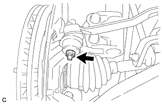
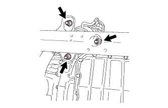
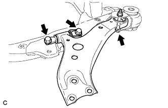
SEPARATE FRONT LOWER NO. 1 SUSPENSION ARM SUB-ASSEMBLY LH
-
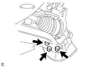
Remove the bolt and 2 nuts, and separate the front lower No. 1 suspension arm sub-assembly from the front lower ball joint assembly.
-
-
SEPARATE FRONT LOWER NO. 1 SUSPENSION ARM SUB-ASSEMBLY RH
Tech Tips
Perform the same procedure as for the LH side
-
SEPARATE FRONT DRIVE SHAFT ASSEMBLY LH
-
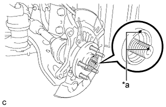
Text in Illustration *a Matchmark Put matchmarks on the front drive shaft assembly and the front axle hub sub-assembly.
-
Using a plastic hammer, separate the front drive shaft assembly from the front axle assembly.
If it is difficult to separate, tap the end of the front drive shaft assembly using a brass bar and a hammer.
-
-
SEPARATE FRONT DRIVE SHAFT ASSEMBLY RH
Tech Tips
Perform the same procedure as for the LH side
-
SEPARATE STEERING INTERMEDIATE SHAFT ASSEMBLY
-
Text in Illustration *a Matchmark Put matchmarks on the steering intermediate shaft assembly and steering link assembly.
-
Remove the bolt.
-
Separate the steering intermediate shaft assembly from the steering link assembly.
-
-
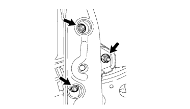
SEPARATE FRONT ENGINE MOUNTING INSULATOR
-
Remove the 3 nuts and separate the front engine mounting insulator from the front frame assembly.
-
-
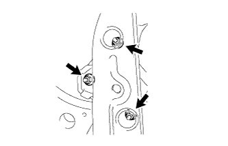
SEPARATE ENGINE MOUNTING INSULATOR LH
-
Remove the 2 hole plugs.
-
Remove the 3 nuts and separate the engine mounting insulator LH from the front frame assembly.
-
-
SEPARATE ENGINE MOUNTING INSULATOR RH
-
Remove the 2 hole plugs.
-
Remove the 3 nuts and separate the engine mounting insulator RH from the front frame assembly.
-
-
REMOVE NO. 2 ENGINE MOUNTING STAY RH
-
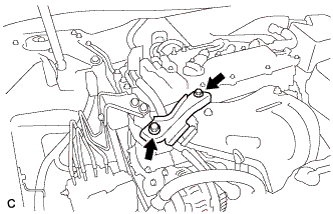
Remove the 2 bolts and No. 2 engine mounting stay RH.
-
-
INSTALL ENGINE HANGERS
-
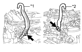
Text in Illustration *1 No. 1 Engine Hanger *2 No. 2 Engine Hanger Install the No. 1 and No. 2 engine hangers with the 2 bolts.
- Torque:
- 33 N*m { 337 kgf*cm, 24 ft.*lbf }
Item Part No. No. 1 engine hanger 12281-31120 No. 2 engine hanger 12281-31100 Bolt 91671-10825
-
-
INSTALL ENGINE SUPPORT BRIDGE
-
Remove the 2 hood support assemblies Click here.
-
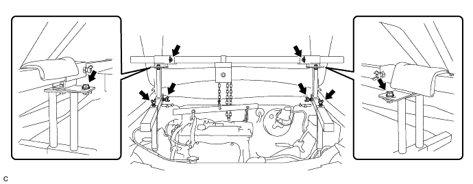
Install SST to the vehicle body as shown in the illustration.
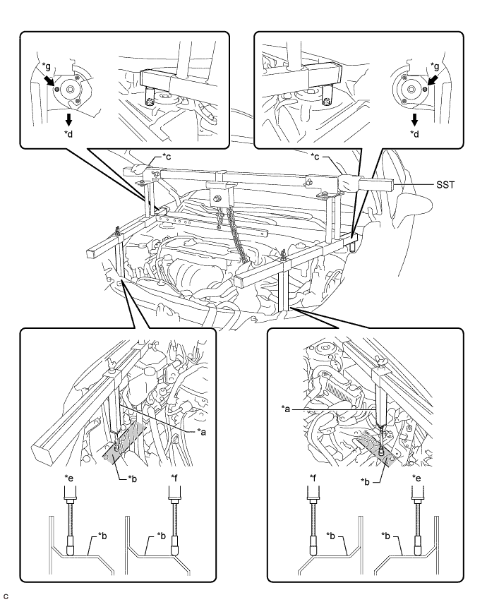
Text in Illustration *a Support Shaft *b Side Member *c Cloth *d Front Side *e Correct *f Incorrect *g Front Suspension Nut - - - SST
- 09940-10020
CAUTION:
Make sure the fuse bolt is not deformed.
Text in Illustration *a Fuse Bolt *b Correct *c Incorrect Note
-
Prevent SST from contacting the vehicle body or windshield.
-
To prevent damage to the engine hood, place pieces of cloth between the engine hood and SST.
-
Lightly shake SST by hand to make sure it is securely installed while performing work.
-
Set the support shafts on level surfaces.
-
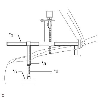
Text in Illustration *a Support Shaft *b Sub Beam *c Side Member *d Threaded Portion Turn the threaded portion of each support shaft to adjust its height and make the SST sub beams parallel to the ground.
-
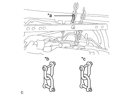
Connect chain to the division bar with the shackles at the positions shown in the illustration.
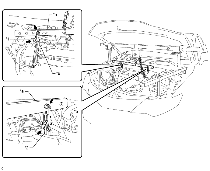
Text in Illustration *1 No. 1 Engine Hanger *2 No. 2 Engine Hanger *a Division Bar *b Shackle -
Connect the division bar and No. 1 engine hanger with the shackle.
-
Connect the 2nd link of the chain to the No. 2 engine hanger.
-
Make sure the distance between the chain block assembly and division bar is 50 mm (1.97 in.) or more.
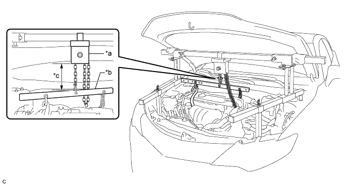
Text in Illustration *a Chain Block Assembly *b Division Bar *c 50 mm (1.97 in.) or more - - -
Adjust the position of the chain block assembly so that the chain is perpendicular to the SST main beam and sub beams as shown in the illustration.
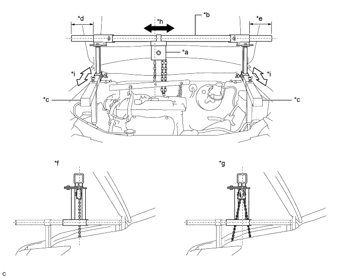
Text in Illustration *a Chain Block Assembly *b Main Beam *c Sub Beam *d Dimension (A) *e Dimension (B) *f Correct *g Incorrect *h Right to Left Adjustment *i Front to Rear Adjustment - - CAUTION:
To prevent the engine with automatic transaxle assembly from falling, make sure that the dimension (A) and dimension (B) are equal.
-
Tighten the 6 wing bolts and 2 bolts.
- Torque:
- for Bolt
- 30 N*m { 306 kgf*cm, 22 ft.*lbf }
-
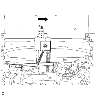
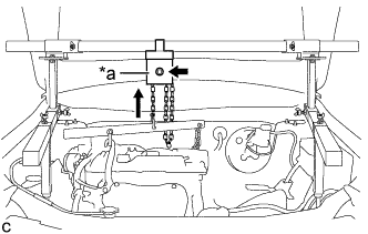
Text in Illustration *a Approximately 50 mm (1.97 in.) Move the chain block assembly approximately 50 mm (1.97 in.) as shown in the illustration.
-
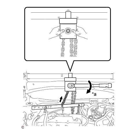
Text in Illustration *a Turn Tighten the chain block assembly until it cannot be moved any further by hand.
Note
-
When suspending the engine with automatic transaxle assembly, do not tighten the chain block assembly more than 50 N*m (510 kgf*cm, 37 ft.*lbf).
-
Do not shake the engine with automatic transaxle assembly excessively while it is being suspended.
-
-
-
INSTALL BELT
-
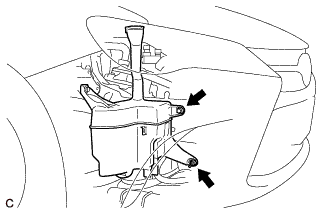
Remove the bolt and nut.
-
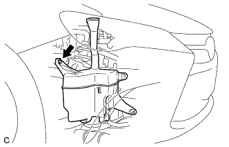
Loosen the bolt and disconnect the windshield washer jar assembly from the vehicle body.
Note
Do not remove the bolt.
-
Install SST to the vehicle body as shown in the illustration.

- SST
- 09727-00110
-
Using the SST ratchet buckle, tighten the SST belt until there is no slack.
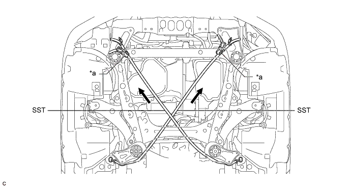
Text in Illustration *a Ratchet Buckle - -
-
-
REMOVE FRONT FRAME ASSEMBLY
-
Text in Illustration *a Chain Block Assembly Wind the chain with the chain block assembly to lift the engine with automatic transaxle assembly.
Note
-
When suspending the engine with automatic transaxle assembly, do not tighten the chain block assembly more than 50 N*m (510 kgf*cm, 37 ft.*lbf).
-
Lift the engine with automatic transaxle assembly until the engine is slightly raised off the front frame assembly.
-
Do not lift the engine with automatic transaxle assembly excessively.
-
-
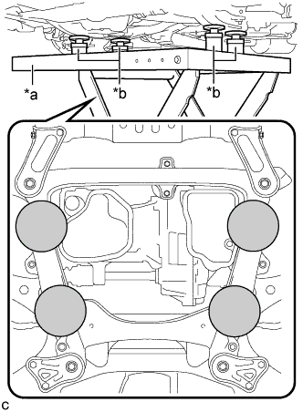
Text in Illustration *a Engine Lifter *b Attachment 
Attachment Placement Location Support the front frame assembly with an engine lifter using 4 attachments or equivalent tools as shown in the illustration.
CAUTION:
-
The front frame assembly is a heavy component. Make sure that it is supported securely.
-
Make sure to secure the front frame assembly to prevent it from dropping.
Note
Use the attachments to keep the front frame assembly level.
-
-
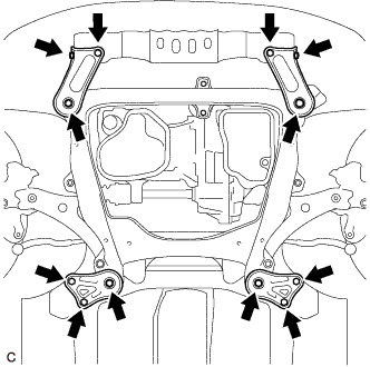
Remove the 4 bolts, 2 nuts and frame side rail plates RH and LH.
-
Remove the 4 bolts, 2 nuts, and front suspension member rear braces RH and LH.
-
Slowly lower the front frame assembly.
Note
When lowering the front frame assembly, be careful not to damage the vehicle body or other components installed to the vehicle.
-
-
REMOVE FRONT NO. 1 STABILIZER BRACKET LH
-
Remove the 2 bolts and front No. 1 stabilizer bracket LH from the front frame assembly.
-
-
REMOVE FRONT NO. 1 STABILIZER BRACKET RH
Tech Tips
Perform the same procedure as for the LH side.
-
REMOVE FRONT STABILIZER BAR WITH FRONT STABILIZER LINK ASSEMBLY
-
Remove the front stabilizer bar with 2 front stabilizer link assemblies from the front frame assembly.
-
-
REMOVE STEERING LINK ASSEMBLY
-
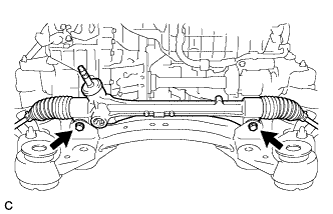
Remove the 2 bolts, 2 nuts and steering link assembly.
Note
Keep the nut from rotating while turning the bolt because the nut has its own stopper.
-
-
REMOVE FRONT LOWER NO. 1 SUSPENSION ARM SUB-ASSEMBLY LH
-
Remove the 3 bolts, nut and front lower No. 1 suspension arm sub-assembly LH from the front frame assembly.
Note
When removing the bolt, keep the nut from rotating.
-
-
REMOVE FRONT LOWER NO. 1 SUSPENSION ARM SUB-ASSEMBLY RH
Tech Tips
Perform the same procedure as for the LH side.
-
REMOVE FRONT SUSPENSION MEMBER DYNAMIC DAMPER
-
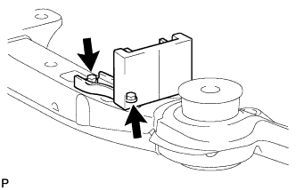
Remove the 2 bolts and front suspension member dynamic damper from the front frame assembly.
-
-
REMOVE FRONT SUSPENSION MEMBER BODY MOUNTING FRONT STOPPER
-
Remove the 2 front suspension member body mounting front stoppers from the front frame assembly.
-
-
REMOVE FRONT SUSPENSION MEMBER BODY MOUNTING REAR STOPPER
-
Remove the 2 front suspension member body mounting rear stoppers from the front frame assembly.
-
-
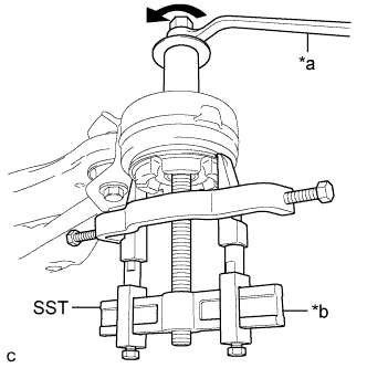
REMOVE FRONT SUSPENSION MEMBER BODY MOUNTING FRONT CUSHION
-
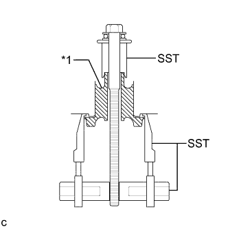
Text in Illustration *1 Front Suspension Member Body Mounting Front Cushion Install SST as shown in the illustration.
- SST
- 09830-10010 ( 09830-01010, 09830-01040, 09830-01050 )
- 09950-40011 ( 09951-04020, 09952-04010, 09954-04010, 09955-04011, 09958-04011 )
-
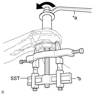
Text in Illustration *a Turn *b Hold Using SST, remove the front suspension member body mounting front cushion from the front frame assembly.
Note
-
Make sure that the claws of SST are securely hung onto the mounting cushion.
-
Tighten SST slowly and evenly.
-
Be careful as the mounting cushion may fly out.
-
The mounting cushion cannot be reused.
-
-
-
REMOVE FRONT SUSPENSION MEMBER BODY MOUNTING REAR CUSHION LH
-
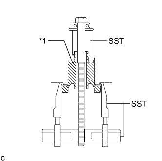
Text in Illustration *1 Front Suspension Member Body Mounting Rear Cushion LH Install SST as shown in the illustration.
- SST
- 09830-10010 ( 09830-01010, 09830-01040, 09830-01050 )
- 09950-40011 ( 09951-04020, 09952-04010, 09954-04010, 09955-04011, 09958-04011 )
-
Text in Illustration *a Turn *b Hold Using SST, remove the front suspension member body mounting rear cushion LH from the front frame assembly.
Note
-
Make sure that the claws of SST are securely hung onto the mounting cushion.
-
Tighten SST slowly and evenly.
-
Be careful as the mounting cushion may fly out.
-
The mounting cushion cannot be reused.
-
-
-
REMOVE FRONT SUSPENSION MEMBER BODY MOUNTING REAR CUSHION RH
Tech Tips
Perform the same procedure as for the LH side.
-
REMOVE HOLE PLUG
-
Remove each hole plug from the front frame assembly.
-