TIRE PRESSURE WARNING SYSTEM, Diagnostic DTC:C2198/98

| DTC Code | DTC Name |
|---|---|
| C2198/98 | Initialization Switch (for Test Mode DTC) |
DESCRIPTION
During test mode, when the tire pressure warning reset switch is on, the tire pressure warning light comes on and when the tire pressure warning reset switch is off, the tire pressure warning light blinks at 0.125 second intervals.
| DTC No. | DTC Detection Condition | Trouble Area |
|---|---|---|
| C2198/98 | Test mode procedure is performed. |
|
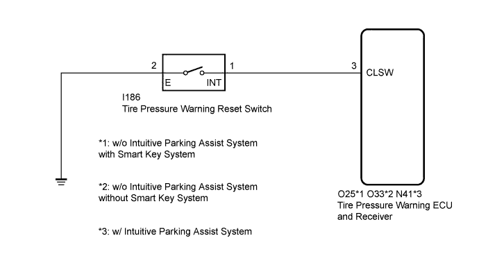
WIRING DIAGRAM
INSPECTION PROCEDURE
Note
-
When replacing the tire pressure warning ECU and receiver, read the transmitter IDs stored in the old ECU using the Techstream and write them down before removal.
-
It is necessary to perform initialization Click here after registration Click here of the transmitter IDs into the tire pressure warning ECU and receiver if the ECU has been replaced.
-
When replacing the tire pressure warning ECU and receiver on vehicles equipped with the wireless door lock control system (w/o smart key system), be sure to perform Registration of Recognition Code to register the transmitter IDs after ECU replacement Click here.
PROCEDURE
-
INSPECT TIRE PRESSURE WARNING RESET SWITCH
-
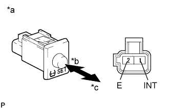
Text in Illustration *a Component without harness connected
(Tire Pressure Warning Reset Switch)
*b On *c Off Disconnect the tire pressure warning reset switch connector.
-
Measure the resistance according to the value(s) in the table below.
Standard Resistance Tester Connection Switch Condition Specified Condition 1 (INT) - 2 (E) On Below 1 Ω Off 10 kΩ or higher
NG 
REPLACE TIRE PRESSURE WARNING RESET SWITCH Click here
OK 
-
-
CHECK HARNESS AND CONNECTOR (RESET SWITCH - TIRE PRESSURE WARNING ECU AND RECEIVER)
-
Disconnect the I186 tire pressure warning reset switch connector and O25, O33 or N41 tire pressure warning ECU and receiver connector.
-
Measure the resistance according to the value(s) in the table below.
Standard Resistance Tester Connection Condition Specified Condition O25-3 (CLSW) - I186-1 (INT)*1
O33-3 (CLSW) - I186-1 (INT)*2
N41-3 (CLSW) - I186-1 (INT)*3
Always Below 1 Ω O25-3 (CLSW) - Body ground*1
O33-3 (CLSW) - Body ground*2
N41-3 (CLSW) - Body ground*3
Always 10 kΩ or higher I186-2 (E) - Body ground Always Below 1 Ω
-
*1: w/o Intuitive Parking Assist System with Smart Key System
-
*2: w/o Intuitive Parking Assist System without Smart Key System
-
*3: w/ Intuitive Parking Assist System
-
NG
REPAIR OR REPLACE HARNESS OR CONNECTOR
OK 
REPLACE TIRE PRESSURE WARNING ECU AND RECEIVER Click here
-