PARK / NEUTRAL POSITION SWITCH REMOVAL

-
REMOVE NO. 1 ENGINE COVER SUB-ASSEMBLY
-
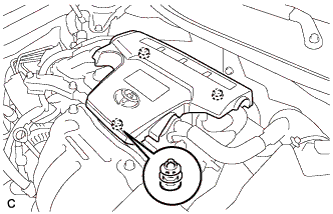
Lift the rear of the No. 1 engine cover sub-assembly to detach the No. 1 engine cover sub-assembly from the 2 pins, and then lift the front of the No. 1 engine cover sub-assembly to detach the No. 1 engine cover sub-assembly from the pin and remove the No. 1 engine cover sub-assembly.
Note
Attempting to disengage both front and rear pins at the same time may cause the No. 1 engine cover sub-assembly to break.
-
-
REMOVE COOL AIR INTAKE DUCT SEAL
-
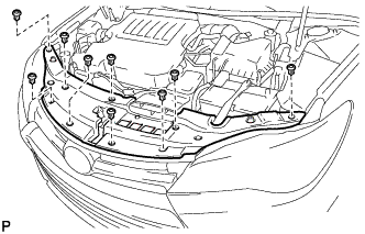
Remove the 9 clips and cool air intake duct seal.
-
-
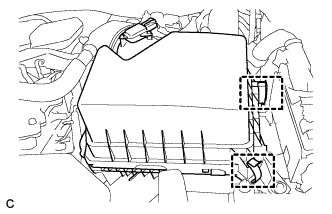
REMOVE INLET AIR CLEANER ASSEMBLY
-
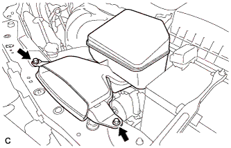
Remove the 2 bolts and inlet air cleaner assembly.
-
-
REMOVE AIR CLEANER CAP SUB-ASSEMBLY
-
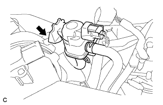
Disconnect the vacuum switching valve assembly from the air cleaner hose.
-
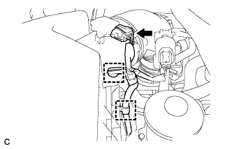
Disconnect the mass air flow meter connector and 2 wire harness clamps from the air cleaner cap sub-assembly.
-
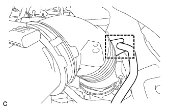
Separate the fuel vapor feed hose from the air cleaner hose.
-
Disconnect the ventilation hose from the cylinder head cover.
-
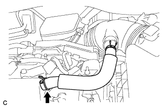
Loosen the hose clamp and disconnect the air cleaner hose from the throttle with motor body assembly.
-
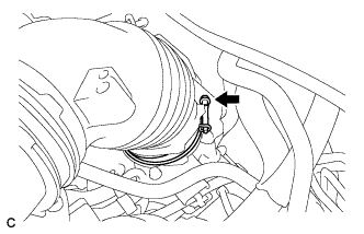
Release the 2 clamps and remove the air cleaner cap sub-assembly.
-
-
REMOVE AIR CLEANER FILTER ELEMENT SUB-ASSEMBLY
-
REMOVE AIR CLEANER CASE SUB-ASSEMBLY
-
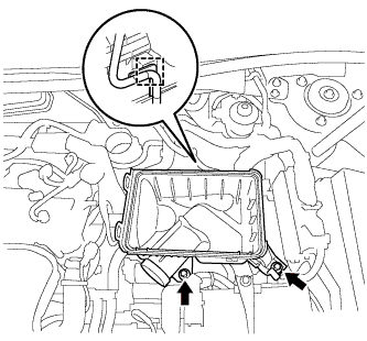
Disconnect the wire harness clamp.
-
Remove the 2 bolts and air cleaner case sub-assembly.
-
-
REMOVE PARK/NEUTRAL POSITION SWITCH ASSEMBLY
-
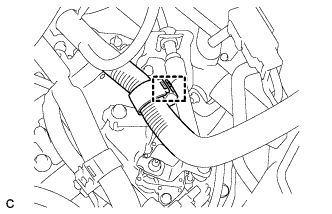
Disconnect the wire harness clamp.
-
Remove the clip from the transmission cable bracket.
-
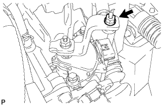
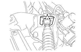
Remove the nut and transmission control cable from the transmission control shaft lever.
-
Disconnect the connector from the park/neutral position switch assembly.
-
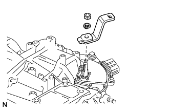
Remove the nut, washer and transmission control shaft lever from the manual valve lever shaft sub-assembly.
-
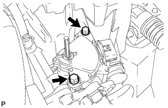
Remove the 2 bolts and park/neutral position switch assembly from the manual valve lever shaft sub-assembly.
Note
Before removing the park/neutral position switch assembly, remove any dirt or rust on the installation portion of the manual valve lever shaft sub-assembly. Be sure to remove the switch straight along the shaft while being careful not to deform the plate spring that supports the shaft. If the plate spring is deformed, the park/neutral switch cannot be reinstalled correctly.
-