AUTOMATIC TRANSAXLE ASSEMBLY (When Using the Engine Support Bridge) INSTALLATION

-
INSTALL TORQUE CONVERTER ASSEMBLY
-
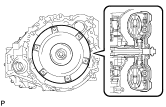
Engage the splines of the input shaft and turbine runner.
-
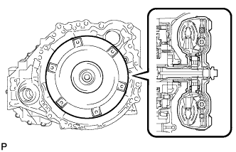
Engage the splines of the stator shaft and the stator while turning the torque converter assembly.
Tech Tips
If the stator shaft splines are difficult to engage with the stator splines, move the torque converter assembly back approximately 10 mm (0.393 in.) and engage the splines while rotating the torque converter assembly.
-
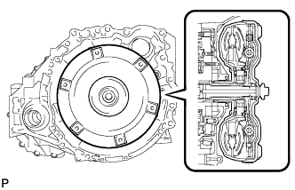
Turn the torque converter assembly to insert the key of the oil pump drive gear into the groove of the torque converter assembly.
-
Clean the torque converter assembly set bolt holes.
-
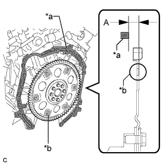
Text in Illustration *a Engine Surface *b Drive Plate Surface Using a vernier caliper and straightedge, measure dimension (A) between the transaxle contact surface of the engine and the torque converter assembly contact surface of the drive plate.
Note
Make sure to deduct the thickness of the straightedge.
-
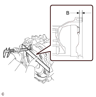
Using a vernier caliper and straightedge, measure dimension (B) shown in the illustration and check that dimension (B) is more than dimension (A), which was measured in the previous step.
Standard Dimension (A) + 1 mm (0.0394 in.) or more Note
-
Make sure to deduct the thickness of the straightedge.
-
If the automatic transaxle assembly is installed to the engine assembly with the torque converter assembly not sufficiently inserted, the torque converter assembly may be damaged.
-
-
-
INSTALL SPEEDOMETER DRIVEN HOLE (ATM) COVER SUB-ASSEMBLY
-
Apply ATF to a new O-ring and install it to the speedometer driven hole (ATM) cover sub-assembly.
-
Install the speedometer driven hole (ATM) cover sub-assembly to the automatic transaxle assembly with the bolt.
- Torque:
- 5.5 N*m { 56 kgf*cm, 49 in.*lbf }
-
-
INSTALL NO. 1 TRANSMISSION CONTROL CABLE BRACKET
-
Install the No. 1 transmission control cable bracket to the automatic transaxle assembly with the 2 bolts.
- Torque:
- 12 N*m { 122 kgf*cm, 9 ft.*lbf }
-
-
INSTALL WIRE HARNESS CLAMP BRACKET
-
Install the 5 wire harness clamp brackets to the automatic transaxle assembly with the 5 bolts.
- Torque:
- 8.0 N*m { 82 kgf*cm, 71 in.*lbf }
-
-
INSTALL FRONT ENGINE MOUNTING BRACKET
-
Install the front engine mounting bracket to the automatic transaxle assembly with the 3 bolts.
- Torque:
- 64 N*m { 653 kgf*cm, 47 ft.*lbf }
-
-
SUPPORT ENGINE ASSEMBLY
-
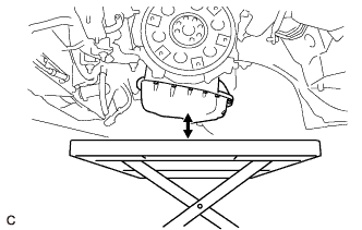
Set an engine lifter.
Note
Make sure that there is a clearance between the engine oil pan assembly and engine lifter.
-
-
INSTALL AUTOMATIC TRANSAXLE ASSEMBLY
-
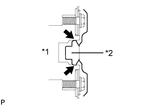
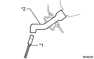
Text in Illustration *1 Crankshaft *2 Torque Converter Assembly Centerpiece Apply clutch spline grease to the circumference of the crankshaft contact surface of the torque converter assembly centerpiece.
Clutch Spline Grease Toyota Genuine Clutch Spline Grease or equivalent Maximum Spread About 1 g (0.0353 oz) -
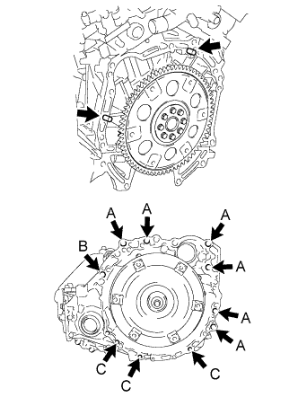
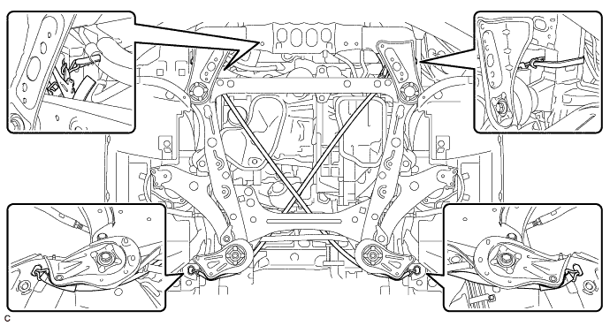
While keeping the engine assembly and automatic transaxle assembly in a horizontal position, align the 2 knock pins with each hole on the automatic transaxle assembly and tighten the 10 bolts shown in the illustration.
- Torque:
- Bolt (A)
- 64 N*m { 653 kgf*cm, 47 ft.*lbf }
- Bolt (B)
- 64 N*m { 653 kgf*cm, 47 ft.*lbf }
- Bolt (C)
- 43 N*m { 438 kgf*cm, 32 ft.*lbf }
Note
-
Confirm that the 2 knock pins are installed to the automatic transaxle assembly contact surface of the engine cylinder block before installing the automatic transaxle assembly.
-
Make sure that the contact surfaces of the engine assembly and automatic transaxle assembly are flat against each other before tightening the bolts.
-
Do not use excessive force when installing the automatic transaxle assembly.
-
Check that the torque converter assembly rotates.
-
Make sure that the wire harness or other similar items are not pinched between the contact surfaces.
-
In order to protect the automatic transaxle oil pan sub-assembly, place attachments on the transmission jack.
-
Make sure that the attachments and automatic transaxle oil pan sub-assembly are centered on the transmission jack.
-
To prevent the automatic transaxle oil pan sub-assembly from being deformed, do not place any attachments under the automatic transaxle oil pan sub-assembly.
-
Secure the automatic transaxle assembly to the transmission jack using a belt, etc. to prevent it from falling.
Bolt Length Bolt (A) 55 mm (2.17 in.) Bolt (B) 50 mm (1.97 in.) Bolt (C) 33 mm (1.30 in.) -
Clean and degrease the bolt and installation hole in the automatic transaxle assembly.
-
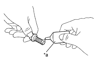
Text in Illustration *a Adhesive Apply adhesive to 2 or 3 threads on the end of the bolt.
Adhesive Toyota Genuine Adhesive 1344, Three Bond 1344 or equivalent -
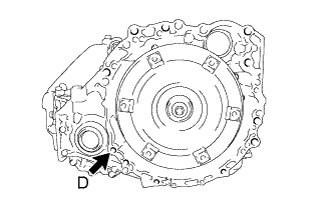
Install the bolt.
- Torque:
- Bolt (D)
- 46 N*m { 469 kgf*cm, 34 ft.*lbf }
Bolt Length Bolt (D) 41 mm (1.61 in.)
-
-
INSTALL BELT
-
Install SST to the vehicle body as shown in the illustration.
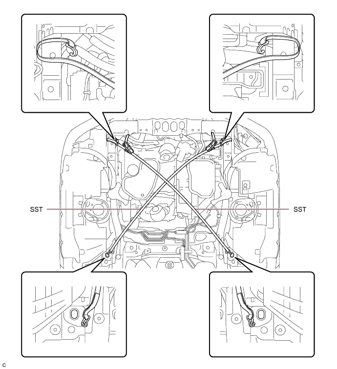
- SST
- 09727-00110
-
Using the SST ratchet buckle, tighten the SST belt until there is no slack.
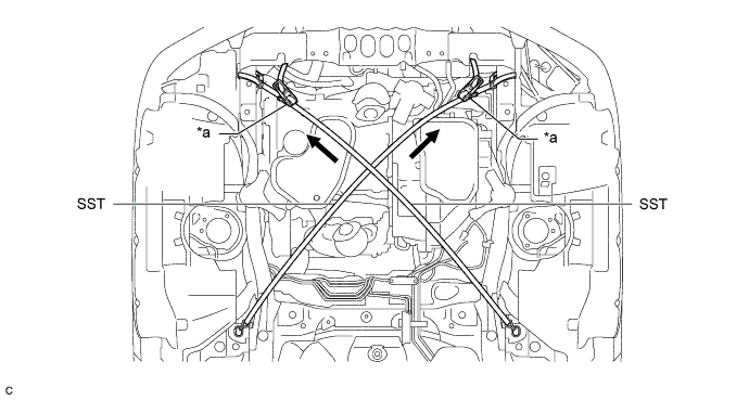
Text in Illustration *a Ratchet Buckle - -
-
-
INSTALL ENGINE MOUNTING INSULATOR LH
-
Install the engine mounting insulator LH to the automatic transaxle assembly with the nut.
- Torque:
- 95 N*m { 969 kgf*cm, 70 ft.*lbf }
-
-
INSTALL FRONT ENGINE MOUNTING INSULATOR ASSEMBLY
-
Install the front engine mounting insulator assembly to the front engine mounting bracket with the bolt.
- Torque:
- 87 N*m { 887 kgf*cm, 64 ft.*lbf }
-
-
REMOVE ENGINE SUPPORT BAR
-
Remove the bolt from the engine mounting bracket RH.
-
Remove the 2 bolts and engine support bar from the vehicle body.
-
-
INSTALL ENGINE MOUNTING INSULATOR RH
-
Install the engine mounting insulator RH to the engine mounting bracket RH with the nut.
- Torque:
- 95 N*m { 969 kgf*cm, 70 ft.*lbf }
-
-
INSTALL FRONT FRAME ASSEMBLY
-
REMOVE BELT
-
Remove SST from the vehicle body.
-
Connect the windshield washer jar assembly to the vehicle body and tighten the bolt.
- Torque:
- 5.5 N*m { 56 kgf*cm, 49 in.*lbf }
-
Install the bolt.
- Torque:
- 5.5 N*m { 56 kgf*cm, 49 in.*lbf }
-
-
REMOVE ENGINE SUPPORT BRIDGE
-
Remove SST from the vehicle body.
Note
Prevent SST from contacting the vehicle body or windshield.
-
Install the 2 hood support assemblies.
-
-
REMOVE ENGINE HANGERS
-
Remove the 4 bolts and No. 1 and No. 2 engine hangers from the engine assembly.
-
-
CONNECT AIR CONDITIONER TUBE AND ACCESSORY ASSEMBLY
-
Connect the air conditioner tube and accessory assembly to the clamp.
-
Remove the vinyl tape from the air conditioner tube and accessory assembly.
-
Sufficiently apply compressor oil to a new O-ring and fitting surface of the air conditioner tube and accessory assembly.
Compressor Oil ND-OIL 8 or equivalent -
Install the O-ring to the air conditioner tube and accessory assembly.
-
Connect the air conditioner tube and accessory assembly.
-
-
CONNECT SUCTION PIPE SUB-ASSEMBLY
-
Connect the suction pipe sub-assembly to the 2 clamps.
-
Remove the vinyl tape from the suction pipe sub-assembly.
-
Sufficiently apply compressor oil to a new O-ring and the fitting surface of the suction pipe sub-assembly.
Compressor Oil ND-OIL 8 or equivalent -
Install the O-ring to the suction pipe sub-assembly.
-
Connect the suction pipe sub-assembly.
-
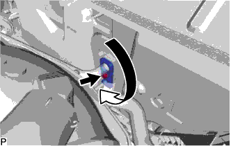
Rotate the hook connector as shown in the illustration.
-
Insert the pipe joint to the fitting hole securely and tighten the bolt.
- Torque:
- 9.8 N*m { 100 kgf*cm, 87 in.*lbf }
-
-
INSTALL INTAKE AIR SURGE TANK ASSEMBLY
-
CONNECT STEERING INTERMEDIATE SHAFT ASSEMBLY
-
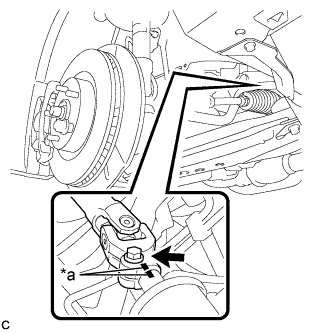
Text in Illustration *a Matchmark Align the matchmarks and install the steering intermediate shaft to the steering link assembly.
-
Install the bolt.
- Torque:
- 35 N*m { 360 kgf*cm, 26 ft.*lbf }
-
-
INSTALL DRIVE PLATE AND TORQUE CONVERTER ASSEMBLY SETTING BOLT
-
Text in Illustration *1 Adhesive 1324 Apply a few drops of adhesive to 2 or 3 threads at the tip of each of the 6 drive plate and torque converter assembly setting bolts.
Adhesive Toyota Genuine Adhesive 1324, Three Bond 1324 or equivalent -
Turn the crankshaft to gain access to the installation locations of the 6 drive plate and torque converter assembly setting bolts and install each bolt while holding the crankshaft pulley bolt with a wrench.
- Torque:
- 41 N*m { 418 kgf*cm, 30 ft.*lbf }
Note
First install the black colored bolt, and then the remaining 5 silver colored bolts.
-
-
INSTALL NO. 1 EXHAUST PIPE SUPPORT BRACKET SUB-ASSEMBLY
-
Install the No. 1 exhaust pipe support bracket sub-assembly with the 2 bolts.
- Torque:
- 7.8 N*m { 80 kgf*cm, 69 in.*lbf }
-
-
INSTALL NO. 1 EXHAUST PIPE SUPPORT BRACKET
-
Install the No. 1 exhaust pipe support bracket with the bolt.
- Torque:
- 21 N*m { 214 kgf*cm, 15 ft.*lbf }
-
-
INSTALL FRONT EXHAUST PIPE ASSEMBLY
-
INSTALL FRONT DRIVE SHAFT HOLE SNAP RING LH
-
Install a new front drive shaft hole snap ring LH.
Note
Face the end gap of the front drive shaft hole snap ring downward.
-
-
INSTALL FRONT DRIVE SHAFT ASSEMBLY
-
INSTALL TRANSMISSION CONTROL CABLE ASSEMBLY
Note
Before installing the transmission control cable assembly, check that the park/neutral position switch and the shift lever are in neutral.
-
Pass the transmission control cable assembly from the cabin to the engine compartment.
-
Install the transmission control cable assembly with the 2 bolts.
- Torque:
- 5.0 N*m { 51 kgf*cm, 44 in.*lbf }
-
Install the dash panel insulator to the original position.
-
Connect the transmission control cable assembly to the transmission control cable bracket with a new clip.
-
Connect the transmission control cable assembly to the control shaft lever with the nut.
- Torque:
- 13 N*m { 130 kgf*cm, 9 ft.*lbf }
Note
Before connecting the transmission control cable assembly, check that the park/neutral position switch and the shift lever are in neutral.
-
Connect the wire harness clamp.
-
Engage the 2 claws to connect the transmission control cable assembly.
-
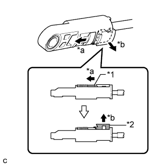
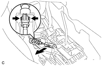
Text in Illustration *1 Slider *2 Lock Piece *a Slide *b Pull Slide the slider of the transmission control cable in the direction indicated by the arrow and pull the lock piece outward.
-
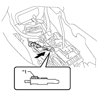
Text in Illustration *1 Lock Piece Install the end of transmission control cable to the lower shift lever assembly.
Note
-
Check that the lock piece is pulled up.
-
Install the cable end all the way to the base of the pin.
-
-
Push the lock piece into the adjuster case.
Note
-
Check that the park/neutral position switch and the shift lever are in neutral.
-
Securely push in the lock piece until the slider lock is engaged.
-
-
-
CONNECT WIRE HARNESS
-
Connect the clamp and front engine mounting insulator assembly connector.
-
Connect the 7 wire harness clamps and park/neutral position switch assembly connector to the automatic transaxle assembly.
-
Connect the wire harness to the automatic transaxle assembly with the bolt.
- Torque:
- 12 N*m { 122 kgf*cm, 9 ft.*lbf }
-
-
INSTALL TCM
-
Install the TCM to the automatic transaxle assembly.
-
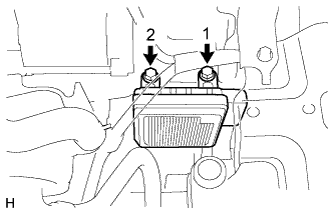
Install and tighten the 2 bolts in the order shown in the illustration.
- Torque:
- 11 N*m { 115 kgf*cm, 8 ft.*lbf }
-
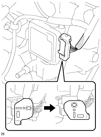
Connect the connector to the TCM.
-
Turn the lock lever and secure the connector with the lock lever.
-
-
INSTALL STARTER ASSEMBLY
-
Install the starter with the 2 bolts.
- Torque:
- 37 N*m { 377 kgf*cm, 27 ft.*lbf }
-
Connect the starter connector.
-
Install the terminal nut and cover the nut with the cap.
- Torque:
- 9.8 N*m { 100 kgf*cm, 87 in.*lbf }
-
-
INSTALL AIR CLEANER BRACKET
-
Install the air cleaner bracket to the battery carrier with the bolt.
- Torque:
- 8.0 N*m { 82 kgf*cm, 71 in.*lbf }
-
Connect the 2 wire clamps.
-
-
INSTALL TRANSMISSION OIL COOLER WITH TRANSMISSION OIL COOLER STAY
-
Install the transmission oil cooler with transmission oil cooler stay to the automatic transaxle assembly with the 2 bolts.
- Torque:
- 14 N*m { 138 kgf*cm, 10 ft.*lbf }
-
Install the No. 1 oil cooler outlet hose and No. 1 oil cooler inlet hose to the transmission oil cooler and automatic transaxle assembly and slide the 4 clamps.
-
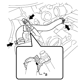
Text in Illustration *a Paint Connect the No. 4 water by-pass hose to the water inlet pipe and transmission oil cooler and slide the 2 clamps.
Note
-
Connect the clamp so that the neck of the clamp is aligned with the paint.
-
Ensure that the paint is completely covered by the clamp.
-
-
Install the clamp and connect the breather plug.
-
-
CONNECT NO. 3 WATER BY-PASS HOSE
-
Connect the No. 3 water by-pass hose to the transmission oil cooler and slide the clip to secure it.
-
-
CONNECT INLET RADIATOR HOSE
-
Connect the inlet radiator hose to the water outlet and slide the clip to secure it.
-
Install the No. 3 water by-pass hose to the inlet radiator hose with the hose clamp.
-
Install the air fuel ratio sensor wire to the inlet radiator hose with the hose clamp.
-
-
INSTALL INLET NO. 1 AIR CLEANER
-
Install the inlet No. 1 air cleaner to the intake air resonator sub-assembly.
-
Engage the pin to the radiator support.
-
-
INSTALL BATTERY
-
Install the battery and battery tray.
-
Install the battery clamp with the bolt and nut.
- Torque:
- Bolt
- 9.0 N*m { 92 kgf*cm, 80 in.*lbf }
- Nut
- 3.5 N*m { 36 kgf*cm, 31 in.*lbf }
-
Connect the cable to the positive (+) battery terminal with the nut.
- Torque:
- 6.9 N*m { 70 kgf*cm, 61 in.*lbf }
-
-
INSTALL AIR CLEANER CASE SUB-ASSEMBLY
-
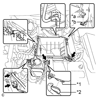
Text in Illustration *1 Air Cleaner Case Sub-assembly *2 Inlet No. 1 Air Cleaner *a Projection *b Hole Install the air cleaner case sub-assembly to the inlet No. 1 air cleaner.
-
Insert the projection of the air cleaner case sub-assembly to the hole of the air cleaner bracket as shown in the illustration.
-
Install the 2 bolts.
- Torque:
- 5.0 N*m { 51 kgf*cm, 44 in.*lbf }
-
Connect the wire harness clamp, connector, vacuum hose and No. 1 fuel vapor feed hose.
-
-
INSTALL AIR CLEANER FILTER ELEMENT SUB-ASSEMBLY
-
INSTALL AIR CLEANER CAP SUB-ASSEMBLY
-
Connect the air cleaner cap sub-assembly to the throttle with motor body assembly with the hose clamp.
-
Install the air cleaner cap with hose to the air cleaner case with the 2 clamps.
-
Connect the wire harness clamp and mass air flow meter connector.
-
Connect the 3 hoses.
-
Connect the ventilation hose.
-
Connect the mass air flow meter connector and wire harness clamp.
-
-
INSTALL INLET NO. 2 AIR CLEANER
-
Install the inlet No. 2 air cleaner to the air cleaner case sub-assembly with the 2 bolts.
- Torque:
- 8.0 N*m { 82 kgf*cm, 71 in.*lbf }
-
Connect the 2 wire harness clamps and vacuum hose clamp.
-
-
CONNECT CABLE FROM NEGATIVE BATTERY TERMINAL
Note
When disconnecting the cable, some systems need to be initialized after the cable is reconnected Click here.
-
INSTALL FRONT WHEELS
-
ADD ENGINE COOLANT
-
Tighten the radiator drain cock plug by hand.
-
Close the 2 cylinder block drain cock plugs.
- Torque:
- 13 N*m { 130 kgf*cm, 9 ft.*lbf }
-
Loosen the air drain cock plug on the water inlet housing.
-
Add TOYOTA Super Long Life Coolant (SLLC) to the radiator inlet opening until coolant overflows from the air drain cock hole. Then tighten the air drain cock plug to the water inlet housing.
- Torque:
- 13 N*m { 130 kgf*cm, 9 ft.*lbf }
-
Slowly fill the radiator with TOYOTA Super Long Life Coolant (SLLC).
Specified capacity 9.1 liters (9.6 US qts, 8.0 lmp. qts) Tech Tips
TOYOTA vehicles are filled with TOYOTA SLLC at the factory. In order to avoid damage to the engine cooling system and other technical problems, only use TOYOTA SLLC or similar high quality ethylene glycol based non-silicate, non-amine, non-nitrite, non-borate coolant with long-life hybrid organic acid technology (coolant with long-life hybrid organic acid technology is a combination of low phosphates and organic acids).
-
Slowly pour coolant into the radiator reserve tank assembly until it reaches the full line.
-
Squeeze the inlet and outlet radiator hoses several times by hand, and then check the level of the coolant.
If the coolant level is low, add coolant.
-
Install the radiator cap sub-assembly and reserve tank cap.
-
Bleed air from the cooling system.
Note
-
Before starting the engine, turn the A/C switch off.
-
Adjust the heater control to the maximum hot setting.
-
Adjust the blower speed to the low setting.
-
Warm up the engine until the thermostat opens. While the thermostat is open, circulate the coolant for several minutes.
Tech Tips
The thermostat open timing can be confirmed by squeezing the outlet radiator hose by hand, and sensing vibrations when the engine coolant starts to flow inside the hose.
-
Maintain the engine speed at 2500 to 3000 rpm.
-
Squeeze the inlet and outlet radiator hoses several times by hand to bleed air.
CAUTION:
When squeezing the radiator hoses:
-
Wear protective gloves.
-
Be careful as the radiator hoses are hot.
-
Keep your hands away from the radiator fans.
Note
-
Make sure that the radiator reserve tank assembly still has some coolant in it.
-
If the coolant temperature gauge indicates an excessive temperature, turn off the engine and let it cool.
-
If there is not enough coolant, the engine may overheat or be seriously damaged.
-
If the radiator reserve tank assembly does not have enough coolant, perform the following: 1) stop the engine, 2) wait until the coolant has cooled down, and 3) add coolant until the reserve tank assembly is filled to the full line.
-
-
-
Stop the engine, and wait until the engine coolant cools down.
-
Add engine coolant to the full line on the radiator reserve tank assembly.
-
-
ADD AUTOMATIC TRANSAXLE FLUID
-
CHARGE AIR CONDITIONING SYSTEM WITH REFRIGERANT
-
WARM UP ENGINE
-
Keep the A/C switch on for at least 2 minutes to warm up the compressor.
Note
To prevent damage to the compressor, be sure to warm up the compressor when turning the air conditioning on after removing and installing air conditioning system lines (including the compressor).
-
-
INSPECT FOR REFRIGERANT LEAK
-
After recharging the air conditioning system with refrigerant, inspect for refrigerant leaks using a halogen leak detector.
-
Carry out the test under the following conditions:
-
Ignition switch off.
-
Secure good ventilation (the halogen leak detector may react to volatile gases which are not refrigerant, such as gasoline vapor and exhaust gas).
-
Repeat the inspection 2 or 3 times.
-
Measure the pressure to make sure that there is some refrigerant remaining in the air conditioning system.
Pressure when the compressor is off: approx. 392 to 588 kPa (4.0 to 6.0 kgf/cm2, 57 to 85 psi)
-
-
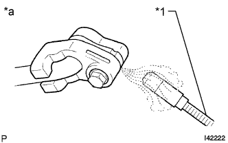
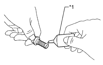
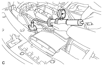
Text in Illustration *1 Halogen Leak Detector *a Inspect for Leak Using a halogen leak detector, inspect for refrigerant leaks from the air conditioning system.
-
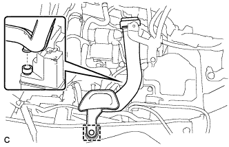
Text in Illustration *1 Halogen Leak Detector *2 Drain Hose Bring the halogen leak detector close to the drain hose with the detector power off, and then turn the detector on.
Tech Tips
-
After the blower motor has stopped, leave the cooling unit for more than 15 minutes.
-
Bring the halogen leak detector sensor under the drain hose.
-
When bringing the halogen leak detector close to the drain hose, make sure that the halogen leak detector does not react to volatile gases. If it is not possible to avoid interference from volatile gases, the vehicle should be lifted up to allow checking for leaks.
-
-
If a refrigerant leak is not detected from the drain hose, remove the blower motor control from the cooling unit. Insert the halogen leak detector sensor into the unit and check for a leak.
-
Disconnect the pressure sensor connector and leave it for approximately 20 minutes. Bring the halogen leak detector close to the pressure sensor and check for a leak.
Tech Tips
When checking for leaks, the presence of oily dirt at a joint can indicate a leak.
-
-
INSPECT ENGINE COOLANT LEVEL IN RESERVOIR
-
Check that the engine coolant level is between the low and full lines when the engine is cold.
If the engine coolant level is low, check for leaks and add "TOYOTA Super Long Life Coolant" or similar high quality ethylene glycol based non-silicate, non-amine, non-nitrite and non-borate coolant with long-life hybrid organic acid technology to the full line.
Note
Do not substitute plain water for engine coolant.
-
-
INSPECT FOR FUEL LEAK
-
Check fuel pump operation.
-
Connect the Techstream to the DLC3.
-
Turn the engine switch on (IG) and turn the Techstream on.
Note
Do not start the engine.
-
Enter the following menus: Powertrain / Engine / Active Test / Control the Fuel Pump / Speed.
-
Check for pressure in the fuel inlet tube from the fuel line. Check that sounds of fuel flowing from the fuel tank can be heard. If no sounds can be heard, check the integration relay, fuel pump, fuel pump control ECU, ECM and wiring connectors.
-
-
Inspect for fuel leaks.
-
Check that there are no fuel leaks from the fuel system after doing any maintenance or repairs. If there is a fuel leak, repair or replace parts as necessary.
-
-
Turn the engine switch off.
-
Disconnect the Techstream from the DLC3.
-
-
INSPECT FOR COOLANT LEAK
CAUTION:
Do not remove the radiator cap sub-assembly while the engine and radiator are still hot. Pressurized, hot engine coolant and steam may be released and cause serious burns.
Note
Before performing each inspection, turn the A/C switch OFF.
-
Fill the radiator with coolant and attach a radiator cap tester.
-
Warm up the engine.
-
Using a radiator cap tester, increase the pressure inside the radiator to 118 kPa (1.2 kgf*cm, 17 psi), and check that the pressure does not drop.
If the pressure drops, check the hoses, radiator and water pump for leaks. If no external leaks are found, check the heater core, cylinder block and cylinder head.
-
-
INSPECT FOR OIL LEAK
-
INSPECT FOR EXHAUST GAS LEAK
-
CHECK FOR SPEED SENSOR SIGNAL
-
INSPECT SHIFT LEVER POSITION
-
When the shift lever is moved from P to R with the engine switch on (IG) and brake pedal depressed, make sure that the shift lever moves smoothly and correctly into position.
-
Start the engine and make sure that the vehicle moves forward when the shift lever is moved from N to D and moves rearward when the shift lever is moved to R.
-
-
ADJUST SHIFT LEVER POSITION
-
Move the shift lever to N.
-
Remove the console box Click here.
-
Disconnect the end of the transmission control cable assembly from the lower shift lever assembly
-
Text in Illustration *1 Slider *2 Lock Piece *a Slide *b Pull Slide the slider of the transmission control cable in the direction indicated by the arrow and pull the lock piece outward.
-
Text in Illustration *1 Lock Piece Install the end of the transmission control cable to the shift lever assembly.
Note
-
Check that the lock piece is pulled up.
-
Install the cable end all the way to the base of the pin.
-
-
Push the lock piece into the adjuster case.
Note
-
Check that the park/neutral position switch and the shift lever are in neutral.
-
Securely push in the lock piece until the slider lock is engaged.
-
-
After adjusting the shift lever position, check the operation and function of the shift lever. If there is a problem, adjust the position again.
-
Install the console box Click here.
-
-
INSPECT AND ADJUST FRONT WHEEL ALIGNMENT
-
INSTALL V-BANK COVER SUB-ASSEMBLY
-
Fit the 3 retainers and install the V-bank cover sub-assembly.
-
-
INSTALL COOL AIR INTAKE DUCT SEAL
-
Install the cool air intake duct seal with the 9 clips.
-
-
INSTALL FRONT OUTER COWL TOP PANEL SUB-ASSEMBLY
-
Install the front outer cowl top panel sub-assembly with the 10 bolts.
- Torque:
- 10 N*m { 102 kgf*cm, 7 ft.*lbf }
-
Engage the 2 clamps to install the wire harness to the front outer cowl top panel sub-assembly.
-
-
INSTALL WINDSHIELD WIPER MOTOR AND LINK ASSEMBLY
-
INSTALL FRONT FENDER APRON SEAL LH
-
INSTALL ENGINE UNDER COVER LH
-
INSTALL FRONT WHEEL OPENING EXTENSION PAD LH
-
INSTALL FRONT FENDER APRON SEAL RH
-
INSTALL ENGINE UNDER COVER RH
-
INSTALL FRONT WHEEL OPENING EXTENSION PAD RH
-
CHECK AUTOMATIC TRANSAXLE SYSTEM
Note
If automatic transaxle assembly parts have been replaced, refer to Parts Replacement Compensation Table to determine if any additional operations are necessary Click here.