AUTOMATIC TRANSAXLE ASSEMBLY (When Using the Engine Support Bridge) REMOVAL

Note
If automatic transaxle assembly parts are replaced, refer to Parts Replacement Compensation Table to determine if any additional operations are necessary Click here.
-
REMOVE REFRIGERANT FROM REFRIGERATION SYSTEM
-
DISCHARGE FUEL PRESSURE
-
ALIGN FRONT WHEELS FACING STRAIGHT AHEAD
-
SECURE STEERING WHEEL
-
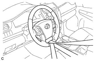
Secure the steering wheel with the seat belt in order to prevent rotation.
Tech Tips
This operation is useful to prevent damage to the spiral cable.
-
-
DISCONNECT CABLE FROM NEGATIVE BATTERY TERMINAL
When disconnecting the cable, some systems need to be initialized after the cable is reconnected Click here.
-
REMOVE FRONT WHEELS
-
REMOVE FRONT WHEEL OPENING EXTENSION PAD RH
-
REMOVE ENGINE UNDER COVER RH
-
REMOVE FRONT FENDER APRON SEAL RH
-
REMOVE FRONT WHEEL OPENING EXTENSION PAD LH
-
REMOVE ENGINE UNDER COVER LH
-
REMOVE FRONT FENDER APRON SEAL LH
-
DRAIN ENGINE COOLANT
Note
Do not remove the radiator cap sub-assembly, cylinder block drain cock plugs and radiator drain cock plug while the engine and radiator are still hot. Pressurized, hot engine coolant and steam may be released and cause serious burns.
-
Loosen the radiator drain cock plug.
-
Loosen the 2 cylinder block drain cock plugs.
-
Remove the radiator cap sub-assembly.
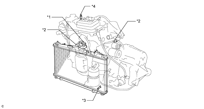
Text in Illustration *1 Radiator Cap Sub-assembly *2 Cylinder Block Drain Cock Plug *3 Radiator Drain Cock Plug *4 Air Drain Cock Plug Tech Tips
Collect the coolant in a container and dispose of it according to the regulations in your area.
-
-
DRAIN AUTOMATIC TRANSAXLE FLUID
-
REMOVE WINDSHIELD WIPER MOTOR AND LINK ASSEMBLY
-
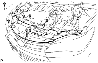
REMOVE FRONT OUTER COWL TOP PANEL SUB-ASSEMBLY
-
Disengage the 2 clamps and separate the wire harness from the front outer cowl top panel sub-assembly.
-

Remove the 10 bolts and front outer cowl top panel sub-assembly.
-
-
REMOVE COOL AIR INTAKE DUCT SEAL
-
Remove the 9 clips and cool air intake duct seal.
-
-
REMOVE V-BANK COVER SUB-ASSEMBLY
-
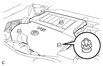
Hold the front of the V-bank cover sub-assembly and raise it to disengage the 2 clips on the front of the V-bank cover sub-assembly. Continue to raise the V-bank cover sub-assembly to disengage the retainer on the rear of the V-bank cover sub-assembly and remove the V-bank cover sub-assembly.
Note
Attempting to disengage both front and rear clips at the same time may cause the V-bank cover sub-assembly to break.
-
-
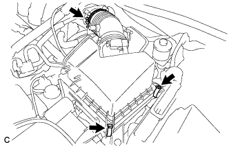
REMOVE INLET NO. 2 AIR CLEANER
-
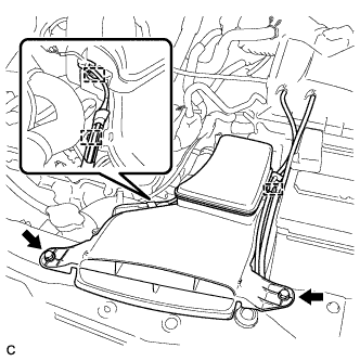
Disconnect the 2 wire harness clamps and vacuum hose clamp.
-
Remove the 2 bolts and inlet No. 2 air cleaner from the air cleaner case sub-assembly.
-
-
REMOVE AIR CLEANER CAP SUB-ASSEMBLY
-
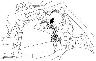
Disconnect the mass air flow meter connector and wire harness clamp.
-
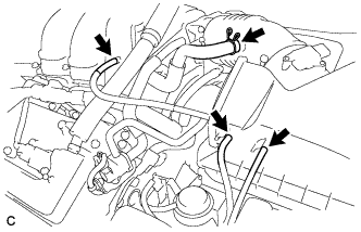
Disconnect the 3 hoses.
-
Separate the ventilation hose.
-
Loosen the hose clamp and separate the air cleaner cap sub-assembly from the throttle with motor body assembly.
-
Release the 2 clamps and remove the air cleaner cap with hose.
-
-
REMOVE AIR CLEANER FILTER ELEMENT SUB-ASSEMBLY
-
REMOVE AIR CLEANER CASE SUB-ASSEMBLY
-
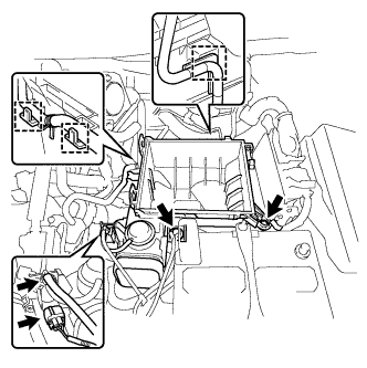
Disconnect the wire harness clamp, connector, vacuum hose and No. 1 fuel vapor feed hose.
-
Remove the 2 bolts and air cleaner case sub-assembly.
-
-
REMOVE BATTERY
-
Loosen the nut, and separate the positive (+) battery terminal.
-
Loosen the nut and remove the bolt and battery clamp.
-
Remove the battery and battery tray.
-
-
REMOVE INLET NO. 1 AIR CLEANER
-
Disengage the pin and remove the inlet No. 1 air cleaner.
-
-
DISCONNECT INLET RADIATOR HOSE
-
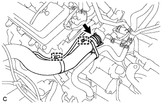
Remove the hose clamp to separate the air fuel ratio sensor wire from the inlet radiator hose.
-
Remove the hose clamp to separate the No. 3 water by-pass hose from the inlet radiator hose.
-
Slide the clip and disconnect the inlet radiator hose from the water outlet.
-
-
DISCONNECT NO. 3 WATER BY-PASS HOSE
-
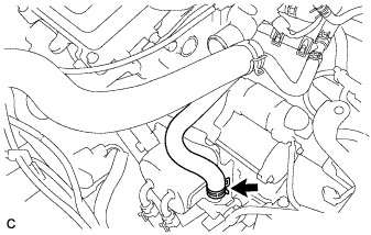
Slide the clip and disconnect the No. 3 water by-pass hose from the transmission oil cooler.
-
-
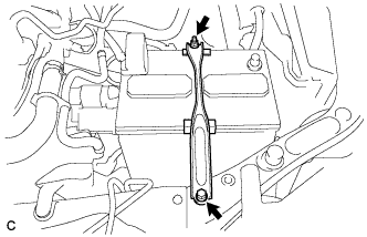
REMOVE TRANSMISSION OIL COOLER WITH TRANSMISSION OIL COOLER STAY
-
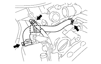
Disconnect the breather plug and remove the clamp.
-
Slide the 2 clamps and remove the No. 4 water by-pass hose from the transmission oil cooler and water inlet pipe.
-
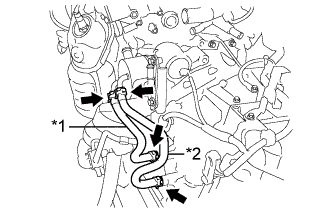
Text in Illustration *1 No. 1 Oil Cooler Outlet Hose *2 No. 1 Oil Cooler Inlet Hose Slide the 4 clamps and remove the No. 1 oil cooler outlet hose and No. 1 oil cooler inlet hose from the transmission oil cooler and automatic transaxle assembly.
-
Remove the 2 bolts and transmission oil cooler with transmission oil cooler stay from the automatic transaxle assembly.
-
-
REMOVE AIR CLEANER BRACKET
-
Disconnect the 2 wire clamps.
-
Remove the bolt and air cleaner bracket from the battery carrier.
-
-
REMOVE STARTER ASSEMBLY
-
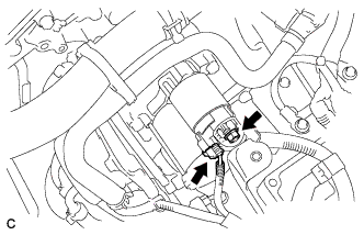
Disconnect the starter connector.
-
Remove the terminal cap.
-
Remove the nut and disconnect the starter wire.
-
Remove the 2 bolts and starter.
-
-
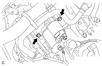
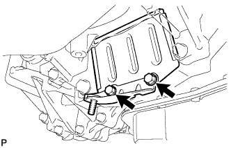
REMOVE TCM
-
Turn the lock lever and disconnect the connector from the TCM.
-
Remove the 2 bolts and TCM from the automatic transaxle assembly.
-
-
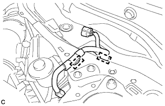
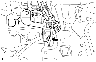
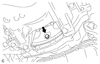
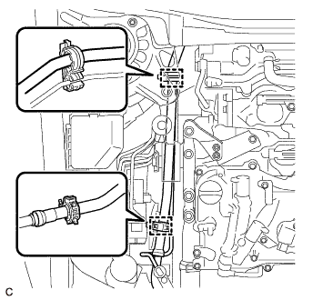
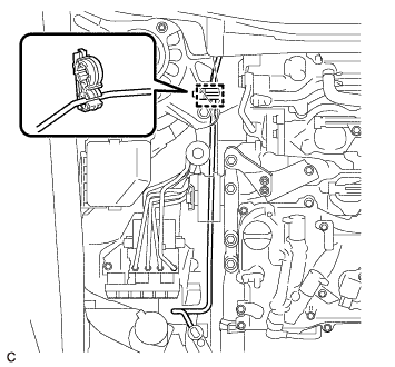
DISCONNECT WIRE HARNESS
-
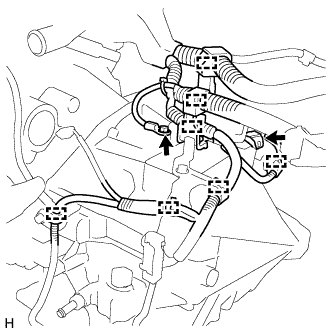
Remove the bolt and disconnect the wire harness from the automatic transaxle assembly.
-
Disconnect the park/neutral position switch assembly connector and disengage the 7 wire harness clamps from the automatic transaxle assembly.
-
Disengage the clamp and disconnect the front engine mounting insulator assembly connector.
-
-
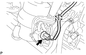
REMOVE TRANSMISSION CONTROL CABLE ASSEMBLY
-
Move the shift lever to N.
-
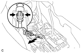
Disconnect the end of the transmission control cable assembly from the lower shift lever assembly.
-
Disengage the 2 claws and disconnect the transmission control cable assembly from the lower shift lever assembly.
-
Disconnect the wire harness clamp.
-
Remove the nut and clip, and disconnect the transmission control cable assembly.
-
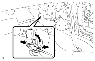
Turn back the dash panel insulator.
-
Remove the 2 bolts and pull out the transmission control cable assembly from the body.
-
-
REMOVE FRONT DRIVE SHAFT ASSEMBLY
-
REMOVE FRONT EXHAUST PIPE ASSEMBLY
-
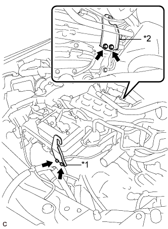
REMOVE NO. 1 EXHAUST PIPE SUPPORT BRACKET
-
Remove the 2 nuts and No. 1 exhaust pipe support bracket (for Front Side).
-
-
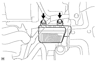
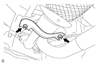
REMOVE NO. 1 EXHAUST PIPE SUPPORT BRACKET SUB-ASSEMBLY
-
Remove the 2 bolts and No. 1 exhaust pipe support bracket sub-assembly.
-
-
REMOVE DRIVE PLATE AND TORQUE CONVERTER ASSEMBLY SETTING BOLT
-
Turn the crankshaft to gain access to the 6 drive plate and torque converter assembly setting bolts and remove each bolt while holding the crankshaft pulley bolt with a wrench.
Tech Tips
There will be one black colored bolt.
-
-
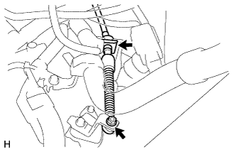
SEPARATE STEERING INTERMEDIATE SHAFT ASSEMBLY
-
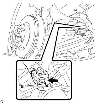
Text in Illustration *a Matchmark Put matchmarks on the steering intermediate shaft assembly and steering link assembly.
-
Remove the bolt.
-
Separate the steering intermediate shaft assembly from the steering link assembly.
-
-
REMOVE INTAKE AIR SURGE TANK ASSEMBLY
-
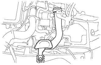
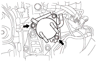
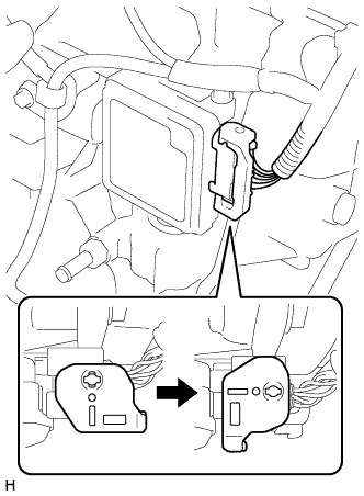
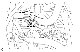
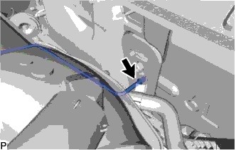
DISCONNECT SUCTION PIPE SUB-ASSEMBLY
-
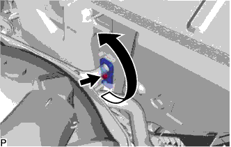
Remove the bolt and rotate the hook connector as shown in the illustration.
-
Disconnect the suction pipe sub-assembly.
-
Remove the O-ring from the suction pipe sub-assembly.
Note
Seal the openings of the disconnected parts using vinyl tape to prevent entry of moisture and foreign matter.
-
Disconnect the suction pipe sub-assembly from the 2 clamps.
-
-
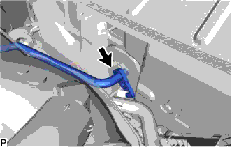
DISCONNECT AIR CONDITIONER TUBE AND ACCESSORY ASSEMBLY
-
Disconnect the air conditioner tube and accessory assembly.
-
Remove the O-ring from the air conditioner tube and accessory assembly.
Note
Seal the openings of the disconnected parts using vinyl tape to prevent entry of moisture and foreign matter.
-
Disconnect the air conditioner tube and accessory assembly from the clamp.
-
-
INSTALL ENGINE HANGERS
-
Text in Illustration *1 No. 2 Engine Hanger *2 No. 1 Engine Hanger Install the No. 1 and No. 2 engine hangers with the 4 bolts.
- Torque:
- 33 N*m { 337 kgf*cm, 24 ft.*lbf }
Item Part No. No. 1 engine hanger 12281-31120 No. 2 engine hanger 12281-31100 Bolt 91671-10825
-
-
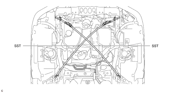
INSTALL ENGINE SUPPORT BRIDGE
-
Remove the 2 hood support assemblies Click here.
-
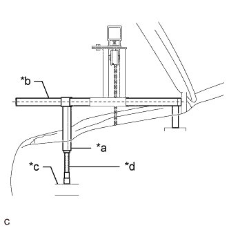
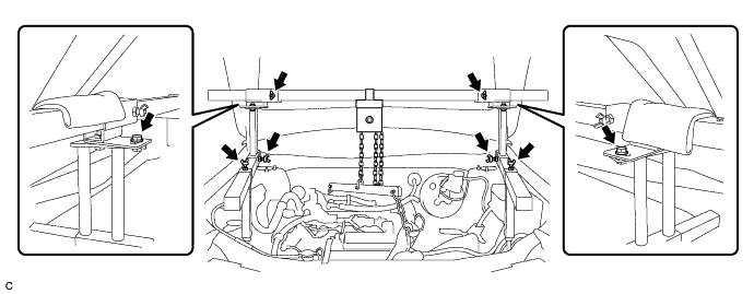
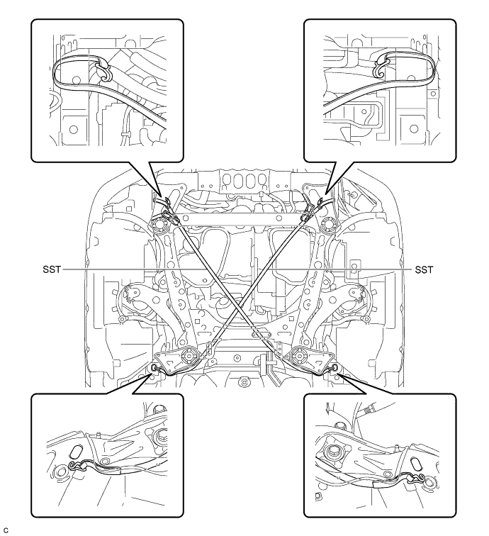
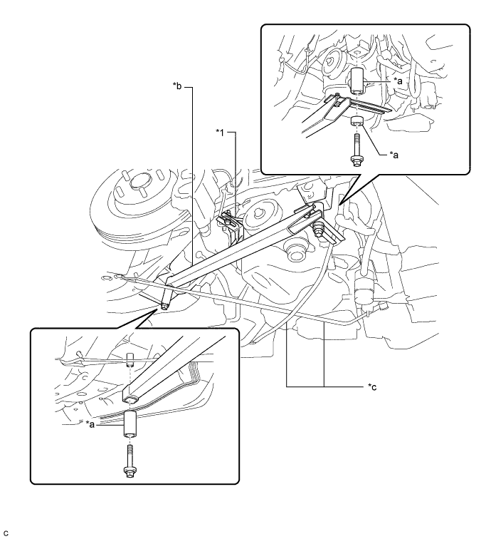
Install SST to the vehicle body as shown in the illustration.
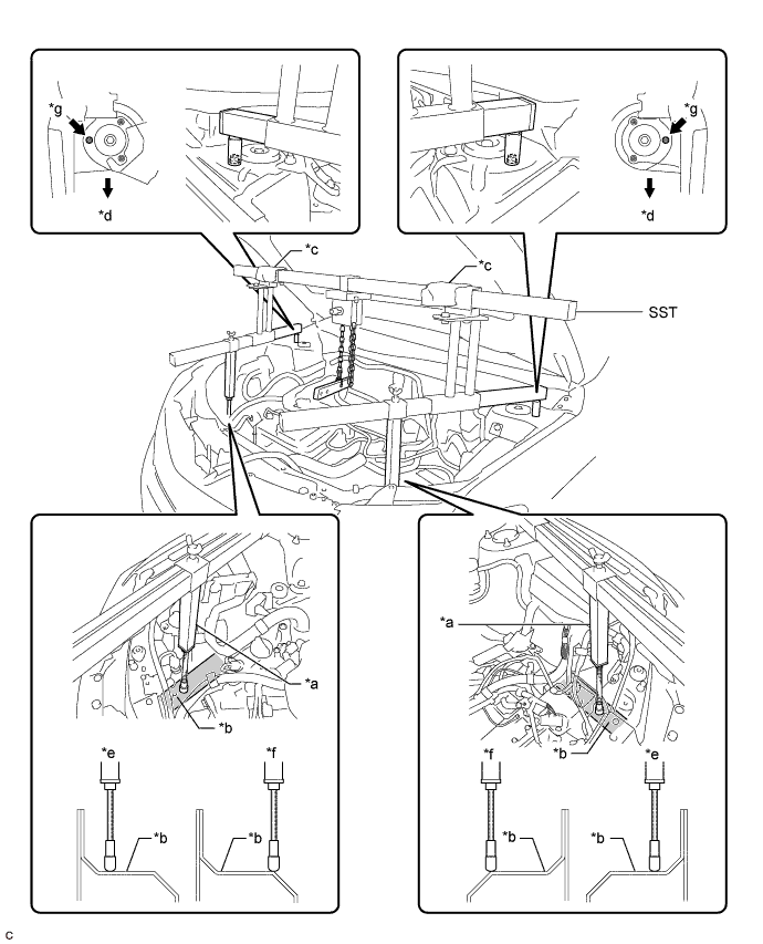
Text in Illustration *a Support Shaft *b Side Member *c Cloth *d Front Side *e Correct *f Incorrect *g Front Suspension Nut - - - SST
- 09940-10020
CAUTION:
Make sure the fuse bolt is not deformed.
Text in Illustration *a Fuse Bolt *b Correct *c Incorrect Note
-
Prevent SST from contacting the vehicle body or windshield.
-
To prevent damage to the engine hood, place pieces of cloth between the engine hood and SST.
-
Lightly shake SST by hand to make sure it is securely installed while performing work.
-
Set the support shafts on level surfaces.
-
Text in Illustration *a Support Shaft *b Sub Beam *c Side Member *d Threaded Portion Turn the threaded portion of each support shaft to adjust its height and make the SST sub beams parallel to the ground.
-
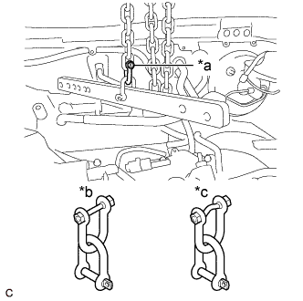
Connect each chain to the division bar with the shackles at the positions shown in the illustration.
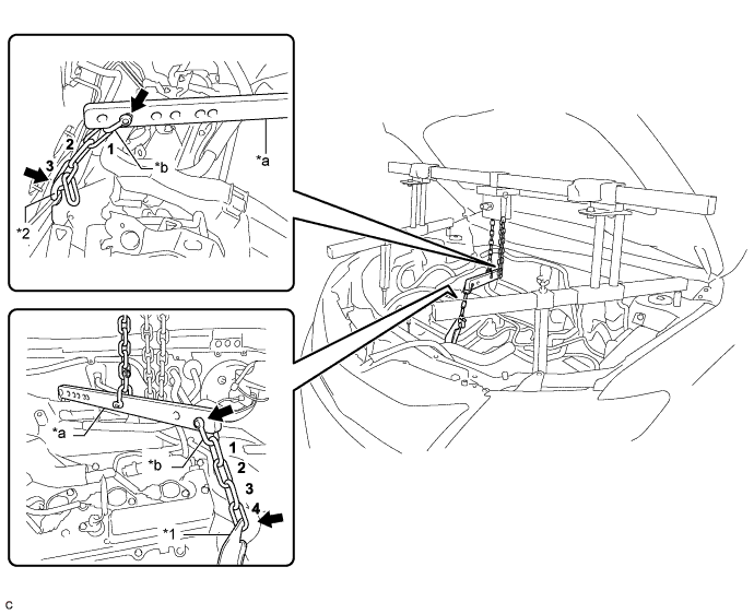
Text in Illustration *1 No. 2 Engine Hanger *2 No. 1 Engine Hanger *a Division Bar *b Shackle -
Connect the 3rd link of the chain to the No. 1 engine hanger.
-
Connect the 4th link of the chain to the No. 2 engine hanger.
-
Make sure the distance between the chain block assembly and division bar is 50 mm (1.97 in.) or more.
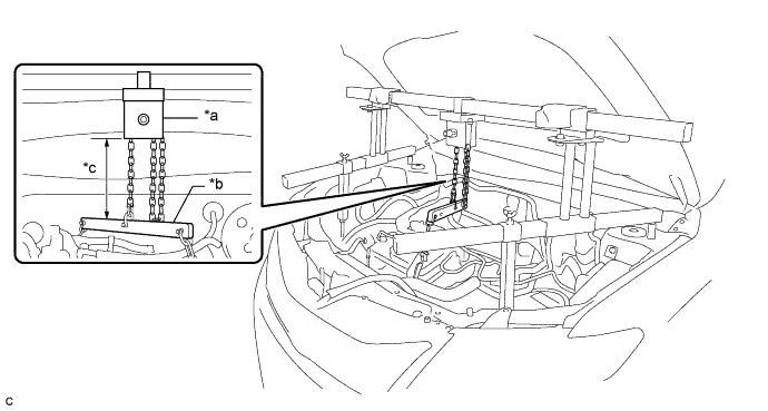
Text in Illustration *a Chain Block Assembly *b Division Bar *c 50 mm (1.97 in.) or more - - -
Adjust the position of the chain block assembly so that the chain is perpendicular to the SST main beam and sub beams as shown in the illustration.
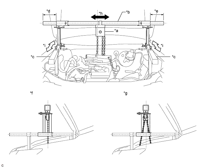
Text in Illustration *a Chain Block Assembly *b Main Beam *c Sub Beam *d Dimension (A) *e Dimension (B) *f Correct *g Incorrect *h Right to Left Adjustment *i Front to Rear Adjustment - - CAUTION:
To prevent the engine with automatic transaxle assembly from falling, make sure that the dimension (A) and dimension (B) are equal.
-
Tighten the 6 wing bolts and 2 bolts.
- Torque:
- for Bolt
- 30 N*m { 306 kgf*cm, 22 ft.*lbf }
-
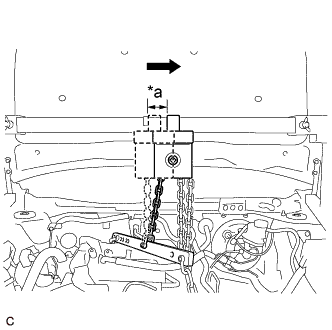
Text in Illustration *a Approximately 50 mm (1.97 in.) Move the chain block assembly approximately 50 mm (1.97 in.) as shown in the illustration.
-
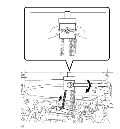
Text in Illustration *a Turn Tighten the chain block assembly until it cannot be moved any further by hand.
Note
-
When suspending the engine with automatic transaxle assembly, do not tighten the chain block assembly more than 50 N*m (510 kgf*cm, 37 ft.*lbf).
-
Do not shake the engine with automatic transaxle assembly excessively while it is being suspended.
-
-
-
INSTALL BELT
-
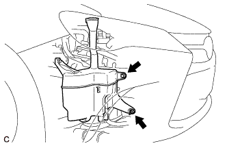
Remove the bolt and nut.
-
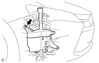
Loosen the bolt and disconnect the windshield washer jar assembly from the vehicle body.
Note
Do not remove the bolt.
-
Install SST to the vehicle body as shown in the illustration.
- SST
- 09727-00110
-
Using the SST ratchet buckle, tighten the SST belt until there is no slack.
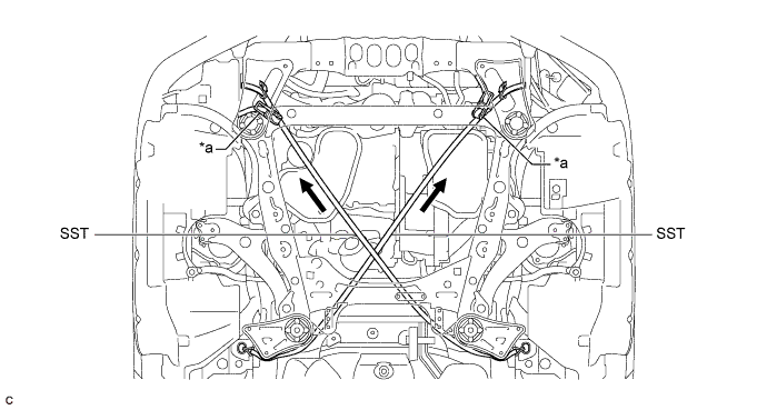
Text in Illustration *a Ratchet Buckle - -
-
-
REMOVE FRONT FRAME ASSEMBLY
-
REMOVE ENGINE MOUNTING INSULATOR RH
-
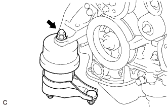
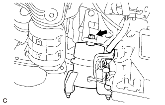
Remove the nut and engine mounting insulator RH from the engine mounting bracket RH.
-
-
INSTALL ENGINE SUPPORT BAR
-
Install the SST (engine support bar) to the vehicle body with the 2 bolts as shown in the illustration.
Text in Illustration *1 Engine Mounting Bracket RH - - *a Spacer *b SST (Support Bar) *c SST (Belt) - - - SST
- 09944-10020
CAUTION:
To prevent the engine with automatic transaxle assembly from falling while servicing, do not remove SST (belt).
-
Install the bolt to the engine mounting bracket RH.
-
-
REMOVE FRONT ENGINE MOUNTING INSULATOR ASSEMBLY
-
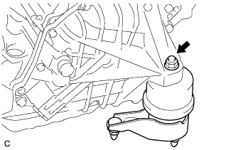
Remove the bolt and front engine mounting insulator assembly from the front engine mounting bracket.
-
-
REMOVE ENGINE MOUNTING INSULATOR LH
-
Remove the nut and engine mounting insulator LH from the automatic transaxle assembly.
-
-
SUPPORT ENGINE ASSEMBLY
-
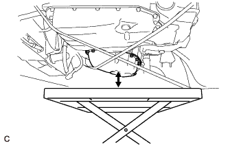
Set an engine lifter.
CAUTION:
To prevent the engine with automatic transaxle assembly from falling while servicing, do not remove SST.
Note
Make sure that there is a clearance between the engine oil pan assembly and engine lifter.
-
-
REMOVE BELT
-
Remove SST from the vehicle body.
-
-
REMOVE AUTOMATIC TRANSAXLE ASSEMBLY
-
Support the automatic transaxle assembly with a transmission jack.
Note
-
In order to protect the automatic transaxle oil pan sub-assembly, place attachments on the transmission jack.
-
Make sure that the attachments and automatic transaxle oil pan sub-assembly are centered on the transmission jack.
-
To prevent the automatic transaxle oil pan sub-assembly from being deformed, do not place any attachments under the automatic transaxle oil pan sub-assembly.
-
-
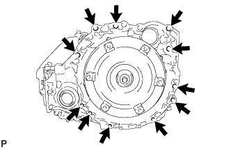
Remove the 11 bolts and automatic transaxle assembly.
Note
-
Secure the automatic transaxle assembly to the transmission jack using a belt, etc. to prevent it from falling.
-
To prevent damage to the 2 knock pins, do not pry between the automatic transaxle assembly and engine assembly.
-
-
-
REMOVE TORQUE CONVERTER ASSEMBLY
-
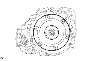
Remove the torque converter assembly from the automatic transaxle assembly.
-
-
INSPECT TORQUE CONVERTER ASSEMBLY
-
Inspect the one-way clutch.
-
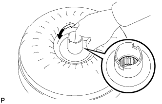
Press on the splines of the stator with a finger and rotate the stator. Check that the stator rotates smoothly when turned clockwise and rotates with difficulty when turned counterclockwise.
If necessary, clean the torque converter and recheck the one-way clutch.
Replace the torque converter if the one-way clutch still fails the inspection.
Text in Illustration 
Difficult 
Smooth
-
-
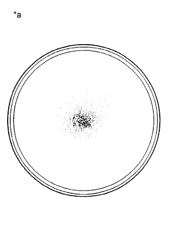
Text in Illustration *a Sample showing maximum allowable amount of powder in ATF Inspect the torque converter assembly.
If any of the following problems are present, replace the torque converter assembly.
-
A metallic sound is emitted from the torque converter assembly during the stall test or when the shift lever is moved to N.
-
The one-way clutch turns smoothly or locks in both directions.
-
The amount of powder in the ATF is more than the sample shown in the illustration (refer to the sample).
Tech Tips
The sample shows approximately 0.025 liters (0.026 US qts, 0.022 Imp. qts) of ATF that was removed from a torque converter.
-
-
Replace the ATF in the torque converter.
Tech Tips
If the ATF is discolored or has a foul odor, stir the ATF in the torque converter before replacing the ATF.
-
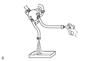
Clean and check the oil cooler and oil pipe line.
Tech Tips
-
If the torque converter is inspected or the ATF is replaced, it is necessary to clean the oil cooler and oil pipe line.
-
Apply compressed air of 196 kPa (2.0 kgf/ cm2, 28 psi) into the inlet hose.
-
If a large amount of powder is found in the ATF, add new ATF using a bucket pump and clean the oil cooler and oil pipe line again.
-
If the ATF is cloudy, inspect the oil cooler.
-
-
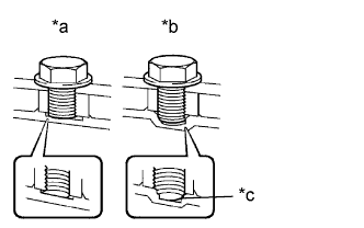
Text in Illustration *a CORRECT *b INCORRECT *c Bottom is damaged Prevent deformation of the torque converter and damage to the oil pump gear.
Note
Make sure that all of the bolts are the same length and that the specified bolts are used.
Tech Tips
If there is any damage to the tip of a bolt for the torque converter or to the bottom of a bolt hole, replace the bolt and torque converter.
-
-
REMOVE FRONT ENGINE MOUNTING BRACKET
-
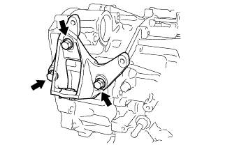
Remove the 3 bolts and front engine mounting bracket from the automatic transaxle assembly.
-
-
REMOVE WIRE HARNESS CLAMP BRACKET
-
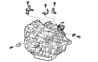
Remove the 5 bolts and 5 wire harness clamp brackets from the automatic transaxle assembly.
-
-
REMOVE NO. 1 TRANSMISSION CONTROL CABLE BRACKET
-
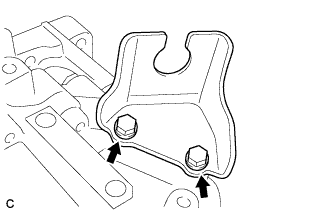
Remove the 2 bolts and No. 1 transmission control cable bracket from the automatic transaxle assembly.
-
-
REMOVE SPEEDOMETER DRIVEN HOLE (ATM) COVER SUB-ASSEMBLY
-
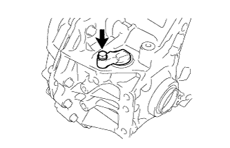
Remove the bolt and speedometer driven hole (ATM) cover sub-assembly from the automatic transaxle assembly.
-
Remove the O-ring from the speedometer driven hole (ATM) cover sub-assembly.
-