AUTOMATIC TRANSAXLE SYSTEM Shift Paddle Switch Circuit
DESCRIPTION
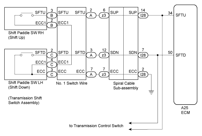
Moving the shift lever to S enables gear selection. The driver can select the gear optionally by shifting the paddle to "+" or "-".
WIRING DIAGRAM
INSPECTION PROCEDURE
PROCEDURE
-
CHECK HARNESS AND CONNECTOR (SHIFT PADDLE SWITCH CIRCUIT)
-
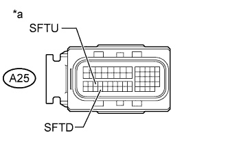
Text in Illustration *a Front view of wire harness connector
(to ECM)
Disconnect the ECM connector.
-
Measure the resistance according to the value(s) in the table below.
Standard Resistance Tester Connection Switch Condition Specified Condition A25- 50 (SFTD) - Body ground Pull "-" continuously
(Down-shift)
Below 1 Ω Release 10 kΩ or higher A25-34 (SFTU) - Body ground Pull "+" continuously
(Up-shift)
Below 1 Ω Release 10 kΩ or higher
NG 
CHECK HARNESS AND CONNECTOR (SPIRAL CABLE - BODY GROUND) Click here
OK 
GO TO TRANSMISSION CONTROL SWITCH CIRCUIT Click here
-
-
CHECK HARNESS AND CONNECTOR (SPIRAL CABLE - BODY GROUND)
-
Disconnect the negative (-) terminal cable from the battery.
-
Wait for at least 90 seconds.
-
Remove the steering wheel assembly.
-
Remove the steering column cover.
-
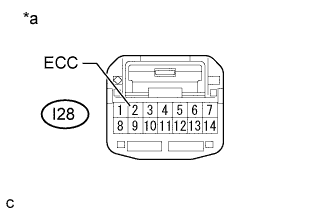
Text in Illustration *a Front view of wire harness connector
(to Spiral Cable Sub-assembly)
Disconnect the spiral cable connector.
-
Measure the resistance according to the value(s) in the table below.
Standard Resistance Tester Connection Condition Specified Condition I28-2 (ECC) - Body ground Always Below 1 Ω
NG 
REPAIR OR REPLACE HARNESS OR CONNECTOR
OK 
-
-
CHECK HARNESS AND CONNECTOR (SPIRAL CABLE - ECM)
-
Disconnect the ECM connector.
-
Measure the resistance according to the value(s) in the table below.
Standard Resistance Tester Connection Switch Condition Specified Condition A25-50 (SFTD) - I28-7 (SDN) Always Below 1 Ω A25-50 (SFTD) or I28-7 (SDN) - Body ground Always 10 kΩ or higher A25-34 (SFTU) - I28-14 (SUP) Always Below 1 Ω A25-34 (SFTU) or I28-14 (SUP) - Body ground Always 10 kΩ or higher
NG
REPAIR OR REPLACE HARNESS OR CONNECTOR
OK
-
-
CHECK HARNESS AND CONNECTOR (SPIRAL CABLE - SHIFT PADDLE SWITCH)
-
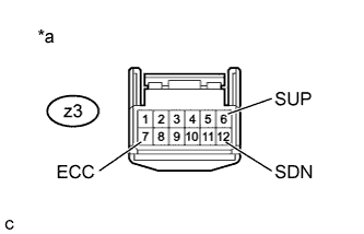
Text in Illustration *a Front view of wire harness connector
(to Spiral Cable Sub-assembly)
Remove the horn button assembly.
-
Disconnect the steering pad switch connector from the spiral cable sub-assembly.
-
Measure the resistance according to the value(s) in the table below when the shift paddle switch is moved to each position.
Standard Resistance Tester Connection Switch Condition Specified Condition z3-6 (SUP) - z3-7 (ECC) Pull "+" continuously
(Up-shift)
Below 1 Ω Release 10 kΩ or higher z3-12 (SDN) - z3-7 (ECC) Pull "-" continuously
(Down-shift)
Below 1 Ω Release 10 kΩ or higher
NG
INSPECT TRANSMISSION SHIFT SWITCH ASSEMBLY (SHIFT PADDLE SWITCH) Click here
OK
-
-
INSPECT SPIRAL CABLE WITH SENSOR SUB-ASSEMBLY
-
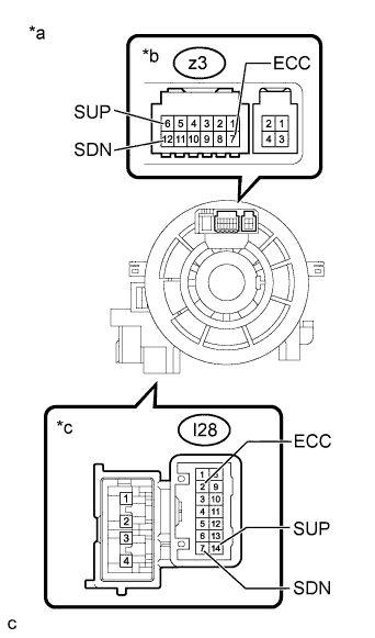
Text in Illustration *a Component without harness connected
(Spiral Cable Sub-assembly)
*b Steering Pad Switch Side *c Vehicle Side Disconnect the steering pad switch connector from the spiral cable sub-assembly.
-
Measure the resistance according to the value(s) in the table below.
Standard Resistance Tester Connection Condition Specified Condition z3-7 (ECC) - I28-2 (ECC) Always Below 3 Ω z3-6 (SUP) - I28-14 (SUP) Always Below 3 Ω z3-12 (SDN) - I28-7 (SDN) Always Below 3 Ω z3-7 (ECC) or I28-2 (ECC) - All other terminals Always 10 kΩ or higher z3-6 (SUP) or I28-14 (SUP) - All other terminals Always 10 kΩ or higher z3-12 (SDN) or I28-7 (SDN) - All other terminals Always 10 kΩ or higher
NG
REPLACE SPIRAL CABLE WITH SENSOR SUB-ASSEMBLY Click here
OK
CHECK FOR INTERMITTENT PROBLEMS Click here
-
-
INSPECT TRANSMISSION SHIFT SWITCH ASSEMBLY (SHIFT PADDLE SWITCH)
-
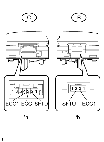
Text in Illustration *a Component without harness connected
(Shift paddle switch LH)
*b Component without harness connected
(Shift paddle switch RH)
Disconnect the connector from the transmission shift switch LH and RH.
-
Measure the resistance according to the value(s) in the table below.
Standard Resistance Transmission Shift Switch LH: Tester Connection Switch Condition Specified Condition C-3 (ECC) - C-2 (SFTD) Pull "-" continuously
(Down-shift)
Below 1 Ω Release 10 kΩ or higher C-4 (ECC1) - C-2 (SFTD) Pull "-" continuously
(Down-shift)
Below 1 Ω Release 10 kΩ or higher Transmission Shift Switch RH: Tester Connection Switch Condition Specified Condition B-3 (SFTU) - B-2 (ECC1) Pull "+" continuously
(Up-shift)
Below 1 Ω Release 10 kΩ or higher
NG
REPLACE TRANSMISSION SHIFT SWITCH ASSEMBLY (SHIFT PADDLE SWITCH) Click here
OK
-
-
INSPECT NO. 1 SWITCH WIRE
-
Connect the transmission shift switch LH and RH connector.
-
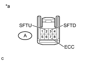
Text in Illustration *a Front view of wire harness connector
(to Steering Pad Switch Connector)
Disconnect the No.1 switch wire from steering pad switch connector.
-
Measure the resistance according to the value(s) in the table below.
Standard Resistance Tester Connection Switch Condition Specified Condition A-3 (SFTD) - A-7 (ECC) Pull "-" continuously
(Down-shift)
Below 1 Ω Release 10 kΩ or higher A-2 (SFTU) - A-7 (ECC) Pull "+" continuously
(Down-shift)
Below 1 Ω Release 10 kΩ or higher
NG
REPLACE NO. 1 SWITCH WIRE Click here
OK
REPAIR OR REPLACE HARNESS OR CONNECTOR (NO. 1 SWITCH WIRE - SPIRAL CABLE SUB-ASSEMBLY)
-