AUTOMATIC TRANSAXLE SYSTEM, Diagnostic DTC:P0560

| DTC Code | DTC Name |
|---|---|
| P0560 | System Voltage |
DESCRIPTION
The battery supplies electricity to the TCM even when the engine switch is off. This power allows the TCM to store data such as DTC history and freeze frame data. If the battery voltage falls below a minimum level, these memories are cleared and the TCM determines that there is a malfunction in the power supply circuit. When the engine is next started, the TCM will illuminate the MIL and set the DTC.
| DTC No. | DTC Detection Condition | Trouble Area |
|---|---|---|
| P0560 | Open in TCM back-up power source circuit. DTC is detected for 3 sec. or more (1 trip detection logic). |
|
Tech Tips
If DTC P0560 is set, the TCM does not store other DTCs.
MONITOR STRATEGY
| Related DTCs | P0560: TCM system voltage |
| Required Sensors/Components (Main) | TCM |
| Required Sensors/Components (Sub) | - |
| Frequency of Operation | Continuous |
| Duration | 3 seconds |
| MIL Operation | Immediate (MIL illuminated after next engine start) |
| Sequence of Operation | None |
TYPICAL ENABLING CONDITIONS
| Monitor runs whenever following DTCs are not present: | None |
| Stand-by RAM | Initialized |
TYPICAL MALFUNCTION THRESHOLDS
| TCM power source | Less than 3.5 V |
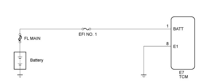
WIRING DIAGRAM
INSPECTION PROCEDURE
Note
-
Perform the universal trip to clear permanent DTCs Click here.
-
Inspect the fuses for circuits related to this system before performing the following inspection procedure.
PROCEDURE
-
CHECK DTC OUTPUT
-
Connect the Techstream to the DLC3.
-
Turn the engine switch on (IG).
-
Turn the Techstream on.
-
Enter the following menus: Powertrain / Engine / Trouble Codes.
-
Read the DTCs using the Techstream.
Result Display (DTC Output) Proceed to No DTC A P0560 is output (engine control system) B
B 
GO TO DTC P0560 (ENGINE CONTROL SYSTEM / SFI SYSTEM) Click here
A 
-
-
INSPECT TCM (POWER SOURCE, GROUND)
-
Disconnect the TCM connector.
-
Measure the voltage according to the value(s) in the table below.
Standard Voltage Tester Connection Condition Specified Condition E7-1 (BATT) - E7-8 (E1) Always 11 to 14 V -
Measure the resistance according to the value(s) in the table below.
Standard Resistance Tester Connection Condition Specified Condition E7-8 (E1) - Body ground Always Below 1 Ω
NG
REPAIR OR REPLACE HARNESS OR CONNECTOR (TCM - BATTERY, BODY GROUND)
OK 
REPLACE TCM Click here
-