DYNAMIC RADAR CRUISE CONTROL SYSTEM, Diagnostic DTC:U0235

| DTC Code | DTC Name |
|---|---|
| U0235 | Lost Communication with Cruise Control Front Distance Range Sensor |
DESCRIPTION
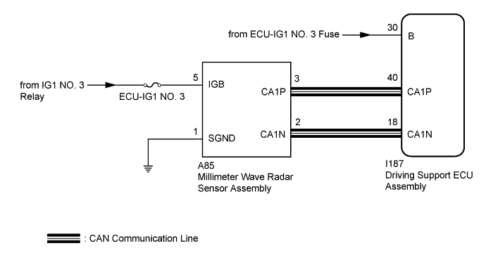
The millimeter wave radar sensor assembly and driving support ECU assembly transmit the data for general vehicle control and diagnosis function via CAN communication. The millimeter wave radar sensor assembly transmits information about the vehicle in front to the driving support ECU assembly.
| DTC No. | Detection Item | DTC Detection Condition | Trouble Area |
|---|---|---|---|
| U0235 | Lost Communication with Cruise Control Front Distance Range Sensor | While dynamic radar cruise control is either preparing for operation or operating and engine switch is on (IG), communication between millimeter wave radar sensor assembly and driving support ECU assembly stops for 1 second or more. |
|
WIRING DIAGRAM
INSPECTION PROCEDURE
Note
-
When the millimeter wave radar sensor assembly is replaced with a new one, adjustment of the radar sensor beam axis must be performed Click here.
-
Inspect the fuses for circuits related to this system before performing the following inspection procedure.
PROCEDURE
-
CHECK CAN COMMUNICATION SYSTEM
-
Using the Techstream, check if the CAN communication system is functioning normally Click here.
Result Result Proceed to CAN communication is normal A CAN communication is malfunctioning B
B 
GO TO CAN COMMUNICATION SYSTEM Click here
A 
-
-
CHECK HARNESS AND CONNECTOR (MILLIMETER WAVE RADAR SENSOR ASSEMBLY POWER SOURCE)
-
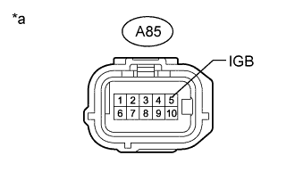
Text in Illustration *a Front view of wire harness connector
(to Millimeter Wave Radar Sensor Assembly)
Disconnect the A85 millimeter wave radar sensor assembly connector.
-
Turn the engine switch on (IG).
-
Measure the voltage according to the value(s) in the table below.
Standard Voltage Tester Connection Condition Specified Condition A85-5 (IGB) - Body ground Engine switch on (IG) 11 to 14 V -
Turn the engine switch off.
-
Reconnect the A85 millimeter wave radar sensor assembly connector.
NG
REPAIR OR REPLACE HARNESS OR CONNECTOR
OK
-
-
CHECK HARNESS AND CONNECTOR (MILLIMETER WAVE RADAR SENSOR ASSEMBLY - BODY GROUND)
-
Disconnect the A85 millimeter wave radar sensor assembly connector.
-
Measure the resistance according to the value(s) in the table below.
Standard Resistance (Check for Open) Tester Connection Condition Specified Condition A85-1 (SGND) - Body ground Always Below 1 Ω -
Reconnect the A85 millimeter wave radar sensor assembly connector.
NG
REPAIR OR REPLACE HARNESS OR CONNECTOR
OK
-
-
CHECK DRIVING SUPPORT ECU ASSEMBLY (B VOLTAGE)
-
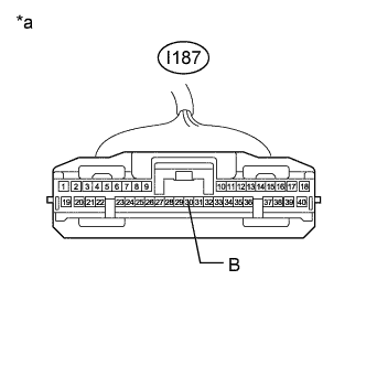
Text in Illustration *a Front view of wire harness connector
(to Driving Support ECU Assembly)
Disconnect the I187 driving support ECU assembly connector.
-
Turn the engine switch on (IG).
-
Measure the voltage according to the value(s) in the table below.
Standard Voltage Tester Connection Condition Specified Condition I187-30 (B) - Body ground Engine switch on (IG) 11 to 14 V -
Turn the engine switch off.
-
Reconnect the I187 driving support ECU assembly connector.
NG
REPAIR OR REPLACE POWER SOURCE CIRCUIT
OK
-
-
REPLACE MILLIMETER WAVE RADAR SENSOR ASSEMBLY
-
Replace the millimeter wave radar sensor assembly Click here.
-
Adjust the millimeter wave radar sensor assembly Click here.
NEXT
-
-
CHECK FOR DTCS (DTC U0235)
-
Connect the Techstream to the DLC3.
-
Turn the engine switch on (IG).
-
Clear the DTCs Click here.
-
Perform the following to make sure that the DTC detection conditions are met.
Tech Tips
If the detection conditions are not met, the malfunction cannot be detected.
-
Drive the vehicle at a speed for which cruise control operation is possible.
-
Turn the dynamic radar cruise control system on using the cruise control main switch (ON-OFF button).
-
Push the cruise control main switch to -SET to activate the dynamic radar cruise control system.
-
-
Enter the following menus: Powertrain / Radar Cruise / Trouble Codes.
-
Check for DTCs.
Result Result Proceed to DTCs are not output A DTC U0235 is output B -
Turn the engine switch off.
B
REPLACE DRIVING SUPPORT ECU ASSEMBLY Click here
A 
END (MILLIMETER WAVE RADAR SENSOR ASSEMBLY WAS DEFECTIVE)
-