DYNAMIC RADAR CRUISE CONTROL SYSTEM, Diagnostic DTC:P1575

| DTC Code | DTC Name |
|---|---|
| P1575 | Warning Buzzer Malfunction |
DESCRIPTION
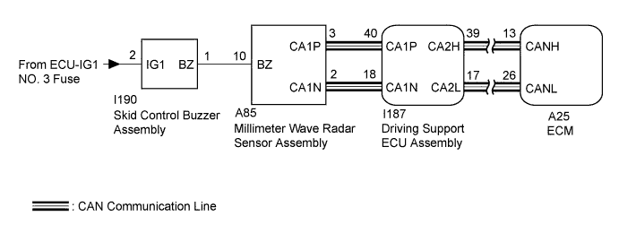
The millimeter wave radar sensor assembly receives an alarm demand signal from the driving support ECU assembly and operates the skid control buzzer assembly. The skid control buzzer assembly sounds to warn that the distance between the vehicle in front and this vehicle is decreasing.
| DTC No. | Detection Item | DTC Detection Condition | Trouble Area |
|---|---|---|---|
| P1575 | Warning Buzzer Malfunction | The ECM receives a buzzer abnormal signal for approximately 0.2 seconds or more while the dynamic radar cruise control is operating. |
|
Tech Tips
If the vehicle ahead in the same lane significantly decreases its speed or another vehicle moves in front of this vehicle, adequate deceleration cannot be applied and the vehicle-to-vehicle distance will shorten. At this time, the system sounds the buzzer and the master warning light blinks to inform the driver. This circuit uses CAN communication. Therefore, if there are any malfunctions in the communication circuit, one or more CAN communication system DTCs are stored.
WIRING DIAGRAM
INSPECTION PROCEDURE
Note
-
When the millimeter wave radar sensor assembly is replaced with a new one, adjustment of the radar sensor beam axis must be performed Click here.
-
If the ECM is replaced, refer to Registration Click here.
-
When replacing the driving support ECU assembly, always replace it with a new one. If a driving support ECU assembly which was installed to another vehicle is used, the information stored in the driving support ECU assembly will not match the information from the vehicle. As a result, a DTC may be stored.
PROCEDURE
-
PERFORM ACTIVE TEST USING TECHSTREAM (RADAR CRUISE APPROACH ALARM BUZZER)
-
Connect the Techstream to the DLC3.
-
Turn the engine switch on (IG).
-
Turn the Techstream on.
-
Enter the following menus: Body Electrical / Pre-Collision 2 / Active Test
-
Perform Active Test according to the display on the Techstream.
Pre-Collision 2 Tester Display Test Part Range Diagnostic Note Radar Cruise Approach Alarm Buzzer Skid control buzzer assembly ON or OFF Buzzer can be heard Result Result Proceed to Skid control buzzer assembly does not sound A Skid control buzzer assembly sounds B -
Turn the engine switch off.
B 
REPLACE DRIVING SUPPORT ECU ASSEMBLY Click here
A 
-
-
INSPECT SKID CONTROL BUZZER ASSEMBLY
-
Remove the skid control buzzer assembly Click here.
-
Inspect the skid control buzzer assembly Click here.
NG
REPLACE SKID CONTROL BUZZER ASSEMBLY Click here
OK
-
-
CHECK TERMINAL VOLTAGE (POWER SOURCE OF SKID CONTROL BUZZER ASSEMBLY)
-
Disconnect the I190 skid control buzzer assembly connector.
-
Measure the voltage according to the value(s) in the table below.
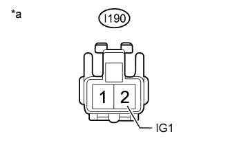
Standard Voltage Tester Connection Condition Specified Condition I190-2 (IG1) - Body ground Engine switch on (IG) 11 to 14 V I190-2 (IG1) - Body ground Engine switch off Below 1 V Text in Illustration *a Front view of wire harness connector
(to Skid Control Buzzer Assembly)
-
Reconnect the I190 skid control buzzer assembly connector.
NG
REPAIR OR REPLACE HARNESS OR CONNECTOR
OK
-
-
CHECK HARNESS AND CONNECTOR (SKID CONTROL BUZZER ASSEMBLY - MILLIMETER WAVE RADAR SENSOR ASSEMBLY)
-
Disconnect the I190 skid control buzzer assembly connector.
-
Disconnect the A85 millimeter wave radar sensor assembly connector.
-
Measure the resistance according to the value(s) in the table below.
Standard Resistance Tester Connection Condition Specified Condition I190-1 (BZ) - A85-10 (BZ) Always Below 1 Ω I190-1 (BZ) or A85-10 (BZ) - Body ground Always 10 kΩ or higher -
Reconnect the A85 millimeter wave radar sensor assembly connector.
-
Reconnect the I190 skid control buzzer assembly connector.
NG
REPAIR OR REPLACE HARNESS OR CONNECTOR
OK
-
-
REPLACE MILLIMETER WAVE RADAR SENSOR ASSEMBLY
-
Replace the millimeter wave radar sensor assembly with a new one Click here.
-
Perform millimeter wave radar sensor assembly adjustment assembly with a new one Click here.
NEXT
-
-
CHECK FOR DTCS (RADAR CRUISE)
-
Connect the Techstream to the DLC3.
-
Turn the engine switch on (IG).
-
Clear the DTCs Click here.
-
Perform the following to make sure that the DTC detection conditions are met.
Tech Tips
If the detection conditions are not met, the malfunction cannot be detected.
-
Drive the vehicle at a speed for which cruise control operation is possible.
-
Turn the dynamic radar cruise control system on using the cruise control main switch (ON-OFF button).
-
Push the cruise control main switch to -SET to activate the dynamic radar cruise control system.
-
-
Enter the following menus: Powertrain / Radar Cruise / Trouble Codes.
-
Check for DTCs.
Result Result Proceed to DTC P1575 is not output A DTC P1575 is output B -
Turn the engine switch off.
B 
REPLACE DRIVING SUPPORT ECU ASSEMBLY Click here
A 
END (MILLIMETER WAVE RADAR SENSOR ASSEMBLY WAS DEFECTIVE)
-
-
REPLACE DRIVING SUPPORT ECU ASSEMBLY
-
Replace the driving support ECU assembly with a new one Click here.
NEXT
-
-
CHECK FOR DTCS (RADAR CRUISE)
-
Connect the Techstream to the DLC3.
-
Turn the engine switch on (IG).
-
Clear the DTCs Click here.
-
Perform the following to make sure that the DTC detection conditions are met.
Tech Tips
If the detection conditions are not met, the malfunction cannot be detected.
-
Drive the vehicle at a speed for which cruise control operation is possible.
-
Turn the dynamic radar cruise control system on using the cruise control main switch (ON-OFF button).
-
Push the cruise control main switch to -SET to activate the dynamic radar cruise control system.
-
-
Enter the following menus: Powertrain / Radar Cruise / Trouble Codes.
-
Check for DTCs.
Result Result Proceed to DTC P1575 is not output A DTC P1575 is output (for 2AR-FE) B DTC P1575 is output (for 2GR-FE) C -
Turn the engine switch off.
B
REPLACE ECM Click here
C
REPLACE ECM Click here
A
END (DRIVING SUPPORT ECU ASSEMBLY WAS DEFECTIVE)
-