EXHAUST MANIFOLD INSTALLATION

-
INSTALL EXHAUST MANIFOLD SUB-ASSEMBLY LH
-
Set a new gasket to the cylinder head sub-assembly.
-
Temporarily install the exhaust manifold sub-assembly LH with the 6 nuts.
-
Temporarily install the No. 2 manifold stay with the bolt and nut.
-
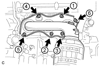
Using a 12 mm deep socket wrench, in several steps, uniformly tighten the 6 nuts in the order shown in the illustration.
- Torque:
- 21 N*m { 214 kgf*cm, 15 ft.*lbf }
-
-
INSTALL NO. 2 MANIFOLD STAY
-
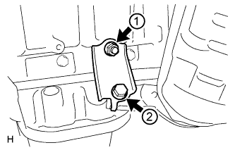
Tighten the bolt and nut in the order shown in the illustration.
- Torque:
- 34 N*m { 347 kgf*cm, 25 ft.*lbf }
-
-
INSTALL NO. 2 EXHAUST MANIFOLD HEAT INSULATOR
-
Install the No. 2 exhaust manifold heat insulator with the 3 bolts.
- Torque:
- 8.5 N*m { 87 kgf*cm, 75 in.*lbf }
-
-
INSTALL NO. 2 ENGINE OIL LEVEL DIPSTICK GUIDE
-
Install a new O-ring to the No. 2 engine oil level dipstick guide.
-
Apply a light coat of engine oil to the O-ring.
-
Push in the No. 2 engine oil level dipstick guide end into the engine oil level dipstick guide.
-
Install the No. 2 engine oil level dipstick guide with the bolt.
- Torque:
- 21 N*m { 214 kgf*cm, 15 ft.*lbf }
-
Install the engine oil level dipstick.
-
-
INSTALL AIR FUEL RATIO SENSOR (for Bank 2)
-
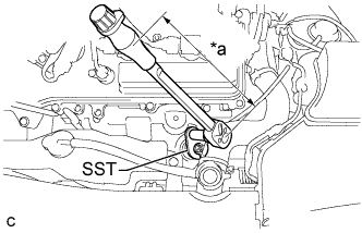
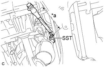
Text in Illustration *a Torque Wrench Fulcrum Length Using SST, install the air fuel ratio sensor to the exhaust manifold LH.
- SST
- 09224-00010
- Torque:
- Specified tightening torque
- 44 N*m { 449 kgf*cm, 33 ft.*lbf }
Tech Tips
-
Calculate the torque wrench reading when changing the fulcrum length of the torque wrench Click here.
-
When using SST (fulcrum length of 30 mm (1.18 in.)) + torque wrench (fulcrum length of 180 mm (7.09 in.)):
40 N*m (408 kgf*cm, 30 ft.*lbf)
-
Perform "Inspection After Repair" after replacing the engine coolant temperature sensor Click here.
-
Connect the air fuel ratio sensor connector.
-
Install the wire harness clamp.
-
-
INSTALL EXHAUST MANIFOLD SUB-ASSEMBLY RH
-
Set a new gasket to the cylinder head sub-assembly.
-
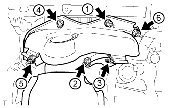
Using a 12 mm deep socket wrench, install the exhaust manifold sub-assembly RH by tightening the 6 nuts in the order shown in the illustration.
- Torque:
- 21 N*m { 214 kgf*cm, 15 ft.*lbf }
-
-
INSTALL AIR FUEL RATIO SENSOR (for Bank 1)
-
Text in Illustration *a Torque Wrench Fulcrum Length Using SST, install the air fuel ratio sensor to the exhaust manifold RH.
- SST
- 09224-00010
- Torque:
- Specified tightening torque
- 44 N*m { 449 kgf*cm, 33 ft.*lbf }
Tech Tips
-
Calculate the torque wrench reading when changing the fulcrum length of the torque wrench Click here.
-
When using SST (fulcrum length of 30 mm (1.18 in.)) + torque wrench (fulcrum length of 180 mm (7.09 in.)):
40 N*m (408 kgf*cm, 30 ft.*lbf)
-
Perform "Inspection After Repair" after replacing the air fuel ratio sensor Click here.
-
Connect the harness clamp.
-
Connect the air fuel ratio sensor connector.
-
-
INSTALL FRONT EXHAUST PIPE ASSEMBLY
-
Install 3 new gaskets to the front exhaust pipe assembly.
-
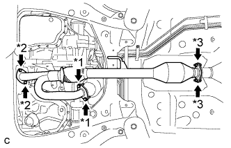
Text in Illustration *1 Bolt *2 Nut *3 Bolt and Nut Install the front exhaust pipe assembly with the 4 bolts and 4 nuts.
- Torque:
- Bolt
- 55 N*m { 561 kgf*cm, 40 ft.*lbf }
- Nut
- 55 N*m { 561 kgf*cm, 40 ft.*lbf }
- Bolt and Nut
- 49 N*m { 500 kgf*cm, 36 ft.*lbf }
-
Install the No. 1 exhaust pipe support bracket with the 2 bolts (for Rear Side).
- Torque:
- 33 N*m { 337 kgf*cm, 24 ft.*lbf }
-
Connect the 2 heated oxygen sensor connectors.
-
Install the 2 wire harnesses to the clamp.
-
-
INSTALL NO. 1 EXHAUST PIPE SUPPORT BRACKET (for Front Side)
-
Install the No. 1 exhaust pipe support bracket with the 2 nuts (for Front Side).
- Torque:
- 33 N*m { 337 kgf*cm, 24 ft.*lbf }
-
-
INSTALL RADIATOR RESERVE TANK ASSEMBLY
-
Install the radiator reserve tank with the 2 bolts.
- Torque:
- 7.0 N*m { 71 kgf*cm, 62 in.*lbf }
-
Connect the radiator reserve tank hose.
-
-
INSTALL ENGINE UNDER COVER RH
-
INSTALL FRONT WHEEL OPENING EXTENSION PAD RH
-
INSPECT FOR EXHAUST GAS LEAK