INTAKE MANIFOLD INSTALLATION

-
INSTALL INTAKE MANIFOLD
-
Set 2 new gaskets on each cylinder head sub-assembly.
Note
-
Align the port holes of the gaskets and cylinder head sub-assembly.
-
Make sure that the gaskets are installed in the correct direction.
-
-
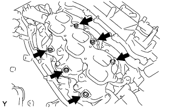
Set the intake manifold on the cylinder head sub-assembly.
-
Install and tighten the 6 bolts and 4 nuts uniformly in several steps.
- Torque:
- 21 N*m { 214 kgf*cm, 15 ft.*lbf }
-
-
INSTALL FUEL DELIVERY PIPE SUB-ASSEMBLY
-
Install 6 new injector vibration insulators to the intake manifold.
-
Place the fuel delivery pipe with the 6 fuel injectors in position on the intake manifold.
Note
Be careful not to drop the fuel injectors when installing the fuel delivery pipe.
-
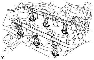
Temporarily install the 5 bolts which are used to hold the fuel delivery pipe to the intake manifold.
Note
After installing the fuel injectors, check that they turn smoothly. If not, reinstall the injectors with new O-rings.
-
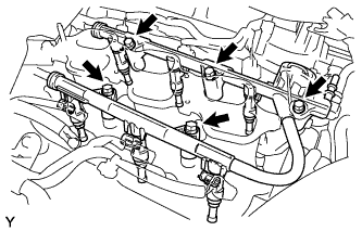
Tighten the 5 bolts which are used to hold the fuel delivery pipe to the intake manifold.
- Torque:
- 21 N*m { 214 kgf*cm, 15 ft.*lbf }
-
Connect the 6 fuel injector connectors.
-
-
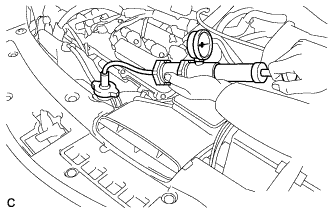
CONNECT FUEL TUBE SUB-ASSEMBLY
-
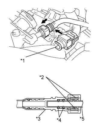
Text in Illustration *1 No. 2 Fuel Pipe Clamp *2 Retainer *3 Fuel Tube Connector *4 O-ring *5 Fuel Pipe 
Push Push in the fuel tube connector onto the pipe until the fuel tube connector makes a "click" sound.
Note
-
Before connecting the fuel tube connector and fuel pipe, check that there is no damage or foreign matter on the connecting part of the fuel pipe.
-
After connecting the fuel tube connector and fuel pipe, check that they are securely connected by trying to pull them apart.
-
-
Install the No. 2 fuel pipe clamp.
-
-
INSTALL NO. 2 ENGINE MOUNTING STAY RH (for Intake Manifold Side)
-
Install the No. 2 engine mounting stay RH with the bolt.
- Torque:
- 21 N*m { 214 kgf*cm, 15 ft.*lbf }
-
-
INSTALL NO. 2 ENGINE MOUNTING STAY RH (for Engine Mounting Stay Side)
-
Install the No. 2 engine mounting stay RH with the bolt.
- Torque:
- 38 N*m { 387 kgf*cm, 28 ft.*lbf }
-
Install the 2 nuts.
- Torque:
- 23 N*m { 234 kgf*cm, 17 ft.*lbf }
-
-
INSTALL INTAKE AIR SURGE TANK ASSEMBLY
Note
DO NOT apply oil to the bolts as listed below
Oil Application Prohibited Bolt Intake Air Surge Tank Assembly and Intake Manifold No. 1 Surge Tank Stay and Intake Air Surge Tank Assembly Throttle Body Bracket and Intake Air Surge Tank Assembly
-
Install 3 new gaskets to the intake air surge tank assembly.
-
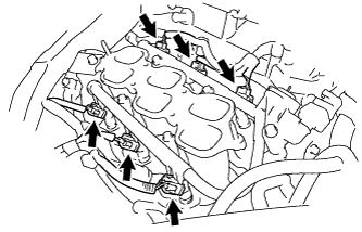
Temporarily install the intake air surge tank assembly with the 4 bolts and 2 nuts.
-
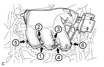
Using a 5 mm hexagon socket wrench, in several steps, uniformly tighten the 4 bolts and 2 nuts in the order shown in the illustration.
- Torque:
- Bolt
- 18 N*m { 184 kgf*cm, 13 ft.*lbf }
- Nut
- 16 N*m { 163 kgf*cm, 12 ft.*lbf }
-
Install the throttle body bracket and No. 1 surge tank stay with the 2 bolts.
- Torque:
- 21 N*m { 214 kgf*cm, 15 ft.*lbf }
-
Install the vacuum hose clamp with the bolt.
- Torque:
- 5.4 N*m { 55 kgf*cm, 48 in.*lbf }
-
Connect the connector to the intake air control valve assembly.
-
Connect the 2 water by-pass hoses and fuel vapor feed hose.
-
Connect the connector and wire harness clamp to the throttle body assembly.
-
Connect the hose clamp and union to check valve hose.
-
Connect the ventilation hose.
-
-
INSTALL AIR CLEANER CAP SUB-ASSEMBLY
-
Connect the air cleaner cap sub-assembly to the throttle with motor body assembly with the hose clamp.
-
Install the air cleaner cap with hose to the air cleaner case with the 2 clamps.
-
Connect the wire harness clamp and mass air flow meter connector.
-
Connect the 3 hoses.
-
Connect the ventilation hose.
-
Connect the mass air flow meter connector and wire harness clamp.
-
-
INSTALL FRONT OUTER COWL TOP PANEL SUB-ASSEMBLY
-
Install the front outer cowl top panel sub-assembly with the 10 bolts.
- Torque:
- 10 N*m { 102 kgf*cm, 7 ft.*lbf }
-
Engage the 2 clamps to install the wire harness to the front outer cowl top panel sub-assembly.
-
-
INSTALL WINDSHIELD WIPER MOTOR AND LINK ASSEMBLY
-
CONNECT CABLE TO NEGATIVE BATTERY TERMINAL
Note
When disconnecting the cable, some systems need to be initialized after the cable is reconnected Click here.
-
ADD ENGINE COOLANT
-
Tighten the radiator drain cock plug by hand.
-
Close the 2 cylinder block drain cock plugs.
- Torque:
- 13 N*m { 130 kgf*cm, 9 ft.*lbf }
-
Loosen the air drain cock plug on the water inlet housing.
-
Add TOYOTA Super Long Life Coolant (SLLC) to the radiator inlet opening until coolant overflows from the air drain cock hole. Then tighten the air drain cock plug to the water inlet housing.
- Torque:
- 13 N*m { 130 kgf*cm, 9 ft.*lbf }
-
Slowly fill the radiator with TOYOTA Super Long Life Coolant (SLLC).
Specified capacity 9.1 liters (9.6 US qts, 8.0 lmp. qts) Tech Tips
TOYOTA vehicles are filled with TOYOTA SLLC at the factory. In order to avoid damage to the engine cooling system and other technical problems, only use TOYOTA SLLC or similar high quality ethylene glycol based non-silicate, non-amine, non-nitrite, non-borate coolant with long-life hybrid organic acid technology (coolant with long-life hybrid organic acid technology is a combination of low phosphates and organic acids).
-
Slowly pour coolant into the radiator reserve tank assembly until it reaches the full line.
-
Squeeze the inlet and outlet radiator hoses several times by hand, and then check the level of the coolant.
If the coolant level is low, add coolant.
-
Install the radiator cap sub-assembly and reserve tank cap.
-
Bleed air from the cooling system.
Note
-
Before starting the engine, turn the A/C switch off.
-
Adjust the heater control to the maximum hot setting.
-
Adjust the blower speed to the low setting.
-
Warm up the engine until the thermostat opens. While the thermostat is open, circulate the coolant for several minutes.
Tech Tips
The thermostat open timing can be confirmed by squeezing the outlet radiator hose by hand, and sensing vibrations when the engine coolant starts to flow inside the hose.
-
Maintain the engine speed at 2500 to 3000 rpm.
-
Squeeze the inlet and outlet radiator hoses several times by hand to bleed air.
CAUTION:
When squeezing the radiator hoses:
-
Wear protective gloves.
-
Be careful as the radiator hoses are hot.
-
Keep your hands away from the radiator fans.
Note
-
Make sure that the radiator reserve tank assembly still has some coolant in it.
-
If the coolant temperature gauge indicates an excessive temperature, turn off the engine and let it cool.
-
If there is not enough coolant, the engine may overheat or be seriously damaged.
-
If the radiator reserve tank assembly does not have enough coolant, perform the following: 1) stop the engine, 2) wait until the coolant has cooled down, and 3) add coolant until the reserve tank assembly is filled to the full line.
-
-
-
Stop the engine, and wait until the engine coolant cools down.
-
Add engine coolant to the full line on the radiator reserve tank assembly.
-
-
INSPECT FOR COOLANT LEAK
CAUTION:
Do not remove the radiator cap sub-assembly while the engine and radiator are still hot. Pressurized, hot engine coolant and steam may be released and cause serious burns.
Note
Before performing each inspection, turn the A/C switch OFF.
-
Fill the radiator with coolant and attach a radiator cap tester.
-
Warm up the engine.
-
Using a radiator cap tester, increase the pressure inside the radiator to 118 kPa (1.2 kgf*cm, 17 psi), and check that the pressure does not drop.
If the pressure drops, check the hoses, radiator and water pump for leaks. If no external leaks are found, check the heater core, cylinder block and cylinder head.
-
-
INSPECT FOR FUEL LEAK
-
Check fuel pump operation.
-
Connect the Techstream to the DLC3.
-
Turn the engine switch on (IG) and turn the Techstream on.
Note
Do not start the engine.
-
Enter the following menus: Powertrain / Engine / Active Test / Control the Fuel Pump / Speed.
-
Check for pressure in the fuel inlet tube from the fuel line. Check that sounds of fuel flowing from the fuel tank can be heard. If no sounds can be heard, check the integration relay, fuel pump, fuel pump control ECU, ECM and wiring connectors.
-
-
Inspect for fuel leaks.
-
Check that there are no fuel leaks from the fuel system after doing any maintenance or repairs. If there is a fuel leak, repair or replace parts as necessary.
-
-
Turn the engine switch off.
-
Disconnect the Techstream from the DLC3.
-
-
INSTALL V-BANK COVER SUB-ASSEMBLY
-
Fit the 3 retainers and install the V-bank cover sub-assembly.
-