ENGINE UNIT INSTALLATION

Tech Tips
Perform "Inspection After Repair" after replacing the engine assembly Click here.
-
INSTALL IGNITION COIL ASSEMBLY
-
Install the 4 ignition coil assemblies with the 4 bolts.
- Torque:
- 10 N*m { 102 kgf*cm, 7 ft.*lbf }
Tech Tips
Perform "Inspection After Repair" after replacing the ignition coil assembly Click here.
-
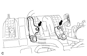
Connect the 4 ignition coil assembly connectors.
-
-
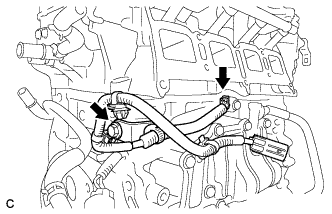
INSTALL ENGINE COOLANT TEMPERATURE SENSOR
-
Install a new gasket to the engine coolant temperature sensor.
-
Using a 19 mm ball joint lock nut wrench, install the engine coolant temperature sensor.
- Torque:
- Specified tightening torque
- 20 N*m { 204 kgf*cm, 15 ft.*lbf }
Tech Tips
-
Calculate the torque wrench reading when changing the fulcrum length of the torque wrench Click here.
-
When using a ball joint lock nut wrench (fulcrum length of 150 mm (5.91 in.)) + torque wrench (fulcrum length of 155 mm (6.1 in.)):
10 N*m (102 kgf*cm, 7 ft.*lbf)
-
Perform "Inspection After Repair" after replacing the engine coolant temperature sensor Click here.
-
Connect the engine coolant temperature sensor connector.
-
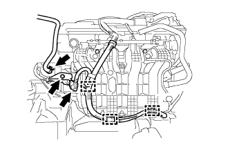
Install the wire harness with the 2 bolts.
- Torque:
- 8.0 N*m { 82 kgf*cm, 71 in.*lbf }
-
-
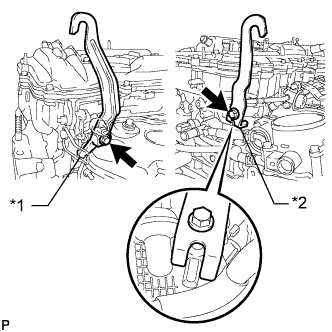
INSTALL ENGINE OIL PRESSURE SWITCH ASSEMBLY
-
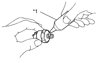
Text in Illustration *1 Adhesive Apply adhesive to 2 or 3 threads of the oil pressure switch.
Adhesive TOYOTA Genuine Adhesive 1344, Three Bond 1344 or equivalent. Note
Do not let adhesive adhere to the oil hole.
-
Using a 24 mm deep socket wrench, install the oil pressure switch.
- Torque:
- 15 N*m { 153 kgf*cm, 11 ft.*lbf }
Note
Do not start the engine within 1 hour of installation.
-
Connect the connector.
-
-
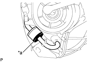
INSTALL KNOCK CONTROL SENSOR
-
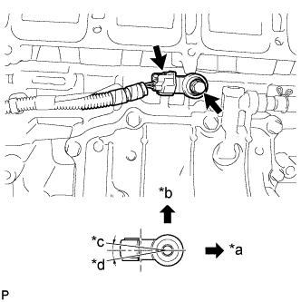
Text in Illustration *a Front of Engine *b Up *c 7° *d 10° Install the sensor with the bolt so that the sensor is angled as shown in the illustration.
- Torque:
- 20 N*m { 204 kgf*cm, 15 ft.*lbf }
Note
The acceptable installation angle of the sensor is between 7° upward and 10° downward from the horizontal position.
Tech Tips
Perform "Inspection After Repair" after replacing the knock control sensor Click here
-
Connect the sensor connector.
-
-
INSTALL SENSOR WIRE
-
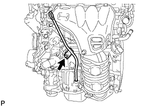
Install the sensor wire with the bolt.
- Torque:
- 21 N*m { 214 kgf*cm, 15 ft.*lbf }
-
Connect the knock control sensor connector.
-
-
INSTALL INTAKE MANIFOLD
-
Install the wire harness clamp bracket with the bolt.
- Torque:
- 8.0 N*m { 82 kgf*cm, 71 in.*lbf }
-
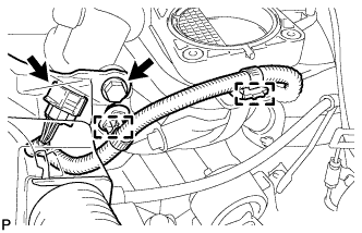
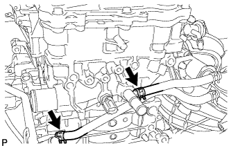
Text in Illustration *a Black Connect the 2 vacuum hoses and check that the No. 1 check valve is installed as shown in the illustration.
-
Check the tumble control valves.
Note
The tumble control valves may be damaged if they are not closed before installing the intake manifold.
Tech Tips
Connect the battery to the terminals of the actuator to operate the motor and close the valves Click here.
-
Install a new intake manifold gasket to the intake manifold.
-
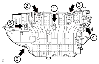
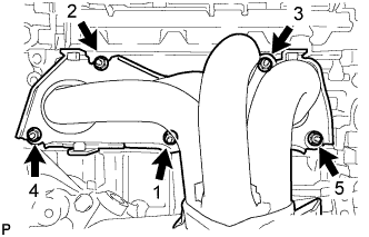
Install the intake manifold by tightening the 6 bolts in the sequence shown in the illustration.
- Torque:
- 21 N*m { 214 kgf*cm, 15 ft.*lbf }
-
Connect the intake air control actuator connector and 2 wire harness clamps.
-
Install the wire harness clamp with the bolt.
- Torque:
- 8.0 N*m { 82 kgf*cm, 71 in.*lbf }
-
Install the wire harness clamp bracket with the bolt.
- Torque:
- 8.0 N*m { 82 kgf*cm, 71 in.*lbf }
-
Connect the 3 wire harness clamps and connector.
-
Connect the fuel vapor feed hose.
-
Install the 2 wire harness clamp brackets with the 2 bolts.
- Torque:
- 8.0 N*m { 82 kgf*cm, 71 in.*lbf }
-
-
INSTALL FUEL INJECTOR ASSEMBLY
-
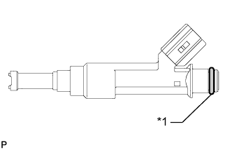
Text in Illustration *1 O-ring Apply a light coat of gasoline or spindle oil to new O-rings, and then install one onto each fuel injector.
-
Apply a light coat of gasoline or spindle oil to the contact surfaces of the new O-ring on each fuel injector assembly.
-
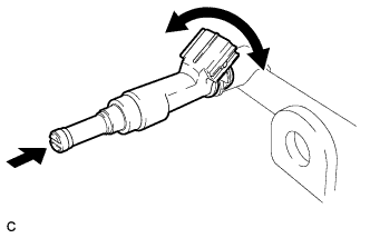
While turning the fuel injector assembly left and right, install it onto the fuel delivery pipe sub-assembly.
Note
Make sure that the O-ring is not cracked or jammed when installing the injector Click here.
Tech Tips
Perform "Inspection After Repair" after replacing the fuel injector assembly Click here.
-
Check that the fuel injector rotates smoothly. If the fuel injector does not rotate, replace the O-ring.
-
-
INSTALL FUEL DELIVERY PIPE SUB-ASSEMBLY
-
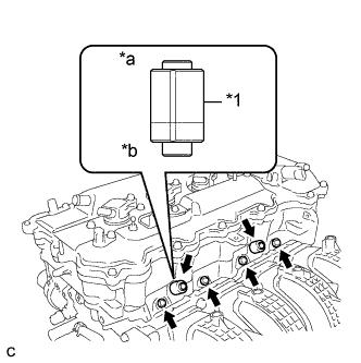
Text in Illustration *1 Fuel Delivery Spacer *a Fuel Delivery Pipe Side *b Cylinder Head Side Install 4 new injector vibration insulators to the cylinder head.
-
Install the 2 fuel delivery spacers onto the cylinder head.
Tech Tips
Install the fuel delivery spacer so that the longer protrusion is on the cylinder head side.
-
Install the fuel delivery pipe sub-assembly with the 4 fuel injector assemblies and install the 2 bolts.
- Torque:
- 21 N*m { 214 kgf*cm, 15 ft.*lbf }
Note
-
Do not drop the fuel injectors when installing the fuel delivery pipe sub-assembly.
-
Check that the fuel injector assemblies rotate smoothly after installing the fuel delivery pipe sub-assembly.
-
-
INSTALL UNION TO CONNECTOR TUBE HOSE
-
Connect the union to connector tube hose to the intake manifold.
-
-
CONNECT NO. 2 VENTILATION HOSE
-
Connect the No. 2 ventilation hose to the intake manifold.
-
-
INSTALL VACUUM SWITCHING VALVE ASSEMBLY (for ACIS)
-
Install the vacuum switching valve assembly with the bolt.
- Torque:
- 9.0 N*m { 92 kgf*cm, 80 in.*lbf }
-
Connect the 2 vacuum hoses and connector.
-
Connect the union to connector tube hose and wire harness clamp.
-
-
INSTALL WATER BY-PASS HOSE
-
Install the No. 1 and No. 2 water by-pass hoses.
-
-
INSTALL THROTTLE WITH MOTOR BODY ASSEMBLY
-
Install a new gasket to the intake manifold.
-
Install the fuel tube bracket with the bolt.
- Torque:
- 13 N*m { 132 kgf*cm, 10 ft.*lbf }
-
Install the throttle with motor body assembly with the 4 bolts.
- Torque:
- 10 N*m { 102 kgf*cm, 7 ft.*lbf }
-
Connect the throttle body connector.
-
Connect the fuel tube to the clamp.
-
Connect the No. 2 water by-pass hose to the throttle with motor body assembly.
-
Connect the water by-pass hose to the throttle with motor body assembly.
-
-
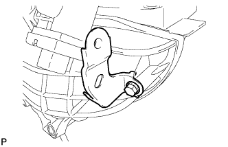
INSTALL NO. 1 COMPRESSOR MOUNTING BRACKET
-
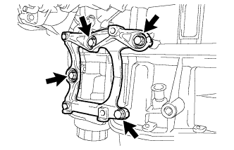
Install the bracket with the 4 bolts.
- Torque:
- 21 N*m { 214 kgf*cm, 15 ft.*lbf }
-
-
INSTALL EXHAUST MANIFOLD CONVERTER SUB-ASSEMBLY
-
Install a new exhaust manifold to head gasket to the cylinder head sub-assembly.
-
Temporarily install the exhaust manifold converter sub-assembly to the cylinder head sub-assembly with the 5 nuts.
-
Tighten the 5 nuts in the order shown in the illustration.
- Torque:
- 35 N*m { 357 kgf*cm, 26 ft.*lbf }
-
-
INSTALL NO. 1 EXHAUST MANIFOLD HEAT INSULATOR
-
Install the No. 1 exhaust manifold heat insulator to the exhaust manifold converter sub-assembly with the 4 bolts.
- Torque:
- 12 N*m { 122 kgf*cm, 9 ft.*lbf }
-
-
INSTALL NO. 2 MANIFOLD STAY
-
Install the No. 2 manifold stay to the exhaust manifold converter sub-assembly and stiffening crankcase assembly with the bolt and nut.
- Torque:
- 43 N*m { 438 kgf*cm, 32 ft.*lbf }
-
-
INSTALL MANIFOLD STAY
-
Install the manifold stay to the exhaust manifold converter sub-assembly and stiffening crankcase assembly with the bolt and nut.
- Torque:
- 43 N*m { 438 kgf*cm, 32 ft.*lbf }
-
-
INSTALL ENGINE OIL LEVEL DIPSTICK GUIDE
-
Apply a light coat of engine oil to a new O-ring.
-
Install the O-ring to the engine oil level dipstick guide.
-
Install the engine oil level dipstick guide with the bolt.
- Torque:
- 10 N*m { 102 kgf*cm, 7 ft.*lbf }
-
Install the engine oil level dipstick.
-
-
INSTALL ENGINE HANGERS
-
Install the 2 engine hangers with the 4 bolts as shown in the illustration.
Part No. Item Part No. No. 1 engine hanger 12281-36020 No. 2 engine hanger 12282-36021 Bolt 91552-81040 or 91552-81025 - Torque:
- 43 N*m { 438 kgf*cm, 32 ft.*lbf }
-
Attach an engine sling device and hang the engine with the chain block.
-