CAMSHAFT REMOVAL

-
DISCONNECT CABLE FROM NEGATIVE BATTERY TERMINAL
Note
When disconnecting the cable, some systems need to be initialized after the cable is reconnected Click here.
-
REMOVE FRONT WHEEL RH
-
REMOVE FRONT WHEEL OPENING EXTENSION PAD RH
-
REMOVE ENGINE UNDER COVER RH
-
REMOVE FRONT FENDER APRON SEAL RH
-
REMOVE COOL AIR INTAKE DUCT SEAL
-
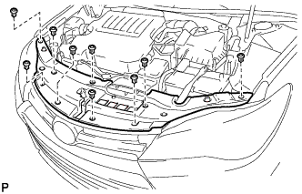
Remove the 9 clips and cool air intake duct seal.
-
-
REMOVE NO. 1 ENGINE COVER SUB-ASSEMBLY
-
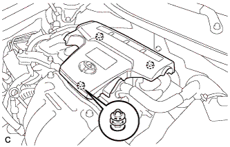
Lift the rear of the No. 1 engine cover sub-assembly to detach the No. 1 engine cover sub-assembly from the 2 pins, and then lift the front of the No. 1 engine cover sub-assembly to detach the No. 1 engine cover sub-assembly from the pin and remove the No. 1 engine cover sub-assembly.
Note
Attempting to disengage both front and rear pins at the same time may cause the No. 1 engine cover sub-assembly to break.
-
-
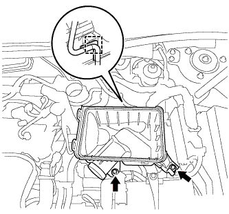
REMOVE INLET AIR CLEANER ASSEMBLY
-
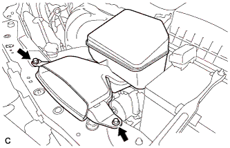
Remove the 2 bolts and inlet air cleaner assembly.
-
-
REMOVE AIR CLEANER CAP SUB-ASSEMBLY
-
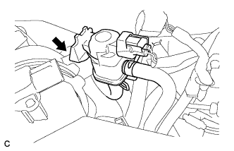
Disconnect the vacuum switching valve assembly from the air cleaner hose.
-
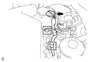
Disconnect the mass air flow meter connector and 2 wire harness clamps from the air cleaner cap sub-assembly.
-
Separate the fuel vapor feed hose from the air cleaner hose.
-
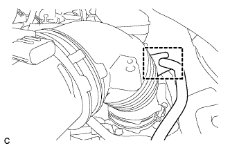
Disconnect the ventilation hose from the cylinder head cover.
-
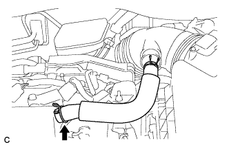
Loosen the hose clamp and disconnect the air cleaner hose from the throttle with motor body assembly.
-
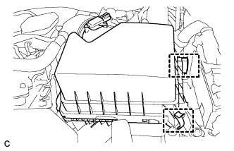
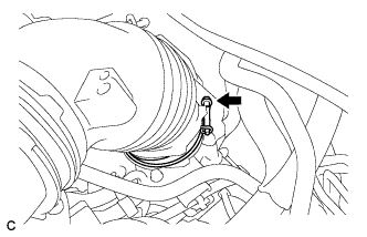
Release the 2 clamps and remove the air cleaner cap sub-assembly.
-
-
REMOVE AIR CLEANER FILTER ELEMENT SUB-ASSEMBLY
-
Remove the air cleaner filter element sub-assembly.
-
-
REMOVE AIR CLEANER CASE SUB-ASSEMBLY
-
Disconnect the wire harness clamp.
-
Remove the 2 bolts and air cleaner case sub-assembly.
-
-
REMOVE NO. 2 ENGINE MOUNTING STAY RH
-
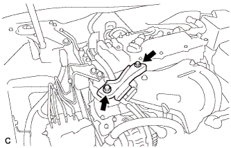
Remove the 2 bolts and No. 2 engine mounting stay RH.
-
-
SEPARATE EARTH WIRE
-
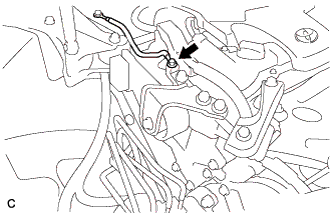
Remove the bolt and separate the earth wire from the engine moving control rod bracket.
-
-
REMOVE ENGINE MOVING CONTROL ROD BRACKET
-
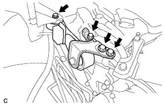
Remove the 4 bolts and engine moving control rod bracket.
-
-
SEPARATE NO. 2 ENGINE ROOM RELAY BLOCK (w/ No. 2 Engine Room Relay Block)
-
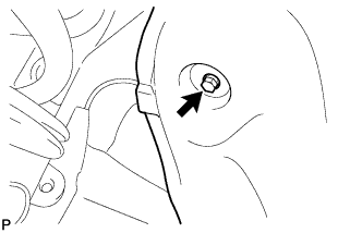
Remove the screw and separate the front fender liner RH.
-
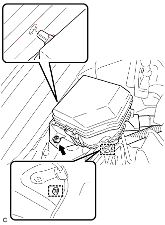
Remove the bolt, disengage the 2 clamps and separate the No. 2 engine room relay block.
-
-
DISCONNECT ENGINE WIRE
-
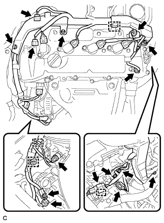
Disconnect the connectors and clamps.
-
Remove the bolts and nuts and disconnect the engine wire from the engine assembly.
-
-
REMOVE IGNITION COIL ASSEMBLY
-
Disconnect the 4 ignition coil assembly connectors.
-
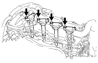
Remove the 4 bolts and 4 ignition coil assemblies.
-
-
REMOVE CYLINDER HEAD COVER SUB-ASSEMBLY
-
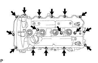
Remove the 16 bolts, 3 seal washers, cylinder head cover and gasket.
-
Remove the 3 gaskets from the camshaft bearing caps.
-
-
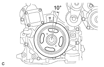
SET NO. 1 CYLINDER TO TDC/COMPRESSION
-
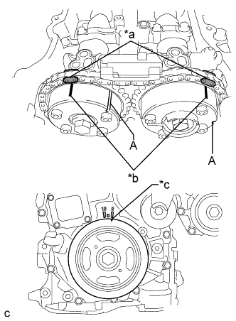
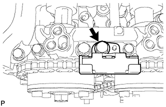
Text in Illustration *a Paint Mark *b Timing Mark *c Timing Notch Turn the crankshaft pulley until its timing notch (groove) and the timing mark "0" of the timing chain cover sub-assembly are aligned.
-
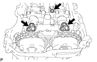
Check that both timing marks on the camshaft timing gear assembly and camshaft timing exhaust gear assembly are facing upward as shown in the illustration. If not, turn the crankshaft 1 revolution (360°) to align the timing marks as shown in the illustration.
Tech Tips
"A" is not a timing mark.
-
Place paint marks on the chain sub-assembly in alignment with the timing marks on the camshaft timing gear assembly and camshaft timing exhaust gear assembly.
-
-
REMOVE TIMING CHAIN COVER PLATE
-
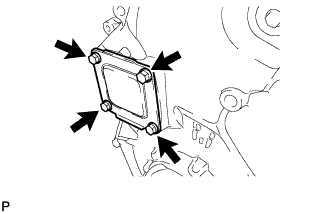
Remove the 4 bolts, timing chain cover plate and gasket.
-
-
REMOVE NO. 1 CHAIN TENSIONER ASSEMBLY
-
Turn the crankshaft pulley approximately 10° clockwise.
-
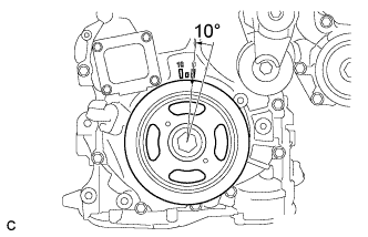
Turn the crankshaft pulley approximately 10° counterclockwise.
-
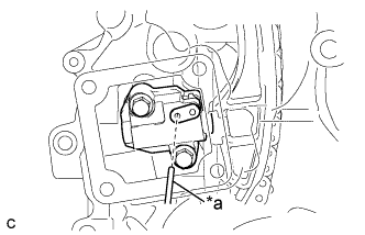
Text in Illustration *a Pin Align the holes of the stopper plate and tensioner, and insert a pin into the stopper plate hole to lock the tensioner.
-
Turn the crankshaft pulley approximately 10° clockwise.
-
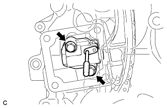
Remove the 2 bolts, No. 1 chain tensioner assembly and gasket.
Note
Make sure not to drop the gasket inside the timing chain cover sub-assembly.
-
Turn the crankshaft pulley approximately 10° counterclockwise.
-
-
REMOVE TIMING CHAIN GUIDE
-
Remove the bolt and timing chain guide.
-
-
REMOVE TIMING CHAIN COVER TIGHT PLUG
-
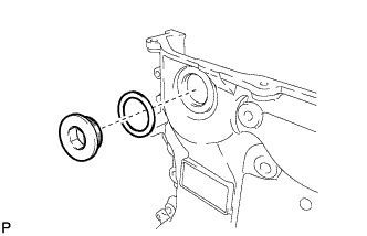
Using a 14 mm hexagon wrench, remove the plug and gasket.
-
-
REMOVE CAMSHAFT TIMING GEAR ASSEMBLY
-
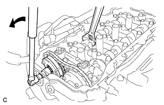
Hold the hexagonal portion of the camshaft with a wrench and remove the bolt from the camshaft.
Note
Be careful not to damage the cylinder head sub-assembly or spark plug tube with the wrench.
-
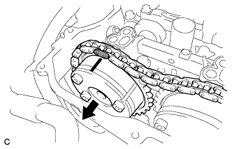
Separate the camshaft timing gear assembly from the camshaft.
-
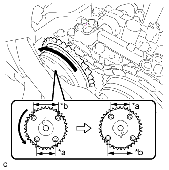
Text in Illustration *a Narrow *b Wide Remove the chain sub-assembly from the camshaft timing gear assembly, and turn the camshaft timing gear assembly approximately 180°.
-
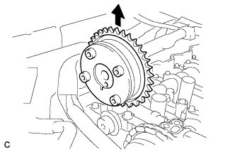
Remove the camshaft timing gear assembly.
Note
Do not disassemble the camshaft timing gear assembly.
-
-
REMOVE CAMSHAFT BEARING CAP
-
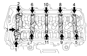
Using several steps, remove the 11 bearing cap bolts in the sequence shown in the illustration.
-
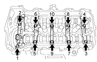
Using several steps, remove the 10 bearing cap bolts in the sequence shown in the illustration.
-
Remove the No. 1 camshaft bearing cap, No. 2 camshaft bearing cap and 3 No. 3 camshaft bearing caps.
Tech Tips
Arrange the removed parts in the correct order.
-
-
REMOVE CAMSHAFT
-
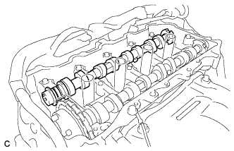
Remove the camshaft from the camshaft housing sub-assembly.
-
-
REMOVE NO. 2 CAMSHAFT
-
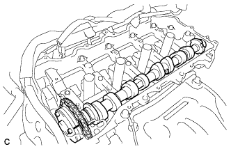
Hold up the chain sub-assembly and remove the No. 2 camshaft from the camshaft housing sub-assembly.
-
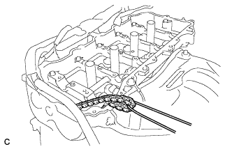
Suspend the chain sub-assembly with a string or equivalent as shown in the illustration.
Note
Be careful not to drop the chain sub-assembly inside the timing chain cover sub-assembly.
-
-
REMOVE CAMSHAFT TIMING EXHAUST GEAR ASSEMBLY
-
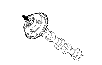
Remove the bolt and camshaft timing exhaust gear assembly.
Note
Do not disassemble the camshaft timing exhaust gear assembly.
-
-
REMOVE OIL CONTROL VALVE FILTER
-
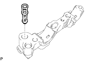
Remove the oil control valve filter from the No. 1 camshaft bearing cap.
-
-
REMOVE NO. 1 CAMSHAFT BEARING
-
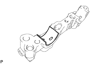
Remove the No. 1 camshaft bearing.
-
-
REMOVE NO. 2 CAMSHAFT BEARING
-
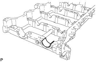
Remove the No. 2 camshaft bearing.
-