SFI SYSTEM Active Control Engine Mount System
DESCRIPTION
LOCATION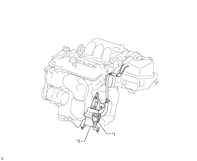
| *1 | Duty Vacuum Switching Valve (for Active Control Engine Mount) | *2 | Front Engine Mounting Insulator Assembly |
The active control engine mount system decreases engine vibration at a low engine speed using the duty vacuum switching valve (for active control engine mount). The duty vacuum switching valve (for active control engine mount) is controlled by a pulse signal transmitted to the duty vacuum switching valve (for active control engine mount) from the ECM. The frequency of this pulse signal is matched to the engine speed to decrease engine vibration.
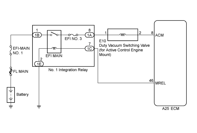
WIRING DIAGRAM
INSPECTION PROCEDURE
Note
Inspect the fuses for circuits related to this system before performing the following inspection procedure.
PROCEDURE
-
CHECK VACUUM HOSES
-
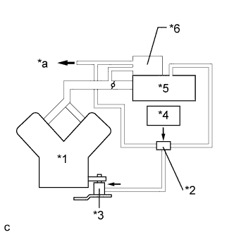
Text in Illustration *1 Engine *2 Duty Vacuum Switching Valve (for Active Control Engine Mount) *3 Front Engine Mounting Insulator Assembly *4 ECM *5 Air Cleaner *6 Vacuum Tank *a to Vacuum Switching Valve (for Air Intake Control Valve) Check the air and vacuum hoses for looseness, disconnection and blockage.
OK No looseness, disconnection or blockage.
NG 
REPAIR OR REPLACE VACUUM HOSES
OK 
-
-
CHECK VACUUM
-
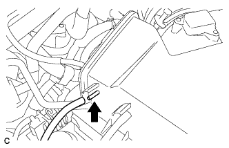
Disconnect the vacuum hose from the air cleaner cap.
-
Start the engine.
-
Check that the disconnected port located on the vacuum tank applies suction to your finger.
OK Vacuum exists.
NG
CHECK AND REPLACE VACUUM SOURCE AND HOSES
OK
-
-
INSPECT DUTY VACUUM SWITCHING VALVE (FOR ACTIVE CONTROL ENGINE MOUNT) (OPERATION)
-
Inspect the duty vacuum switching valve (for active control engine mount) operation Click here.
NG
REPLACE DUTY VACUUM SWITCHING VALVE (FOR ACTIVE CONTROL ENGINE MOUNT) Click here
OK
-
-
INSPECT DUTY VACUUM SWITCHING VALVE (FOR ACTIVE CONTROL ENGINE MOUNT) (RESISTANCE)
-
Inspect the duty vacuum switching valve (for active control engine mount) resistance Click here.
NG
REPLACE DUTY VACUUM SWITCHING VALVE (FOR ACTIVE CONTROL ENGINE MOUNT) Click here
OK
-
-
INSPECT FRONT ENGINE MOUNTING INSULATOR ASSEMBLY
-
Inspect the front engine mounting insulator assembly Click here.
NG
REPLACE FRONT ENGINE MOUNTING INSULATOR ASSEMBLY Click here
OK
-
-
CHECK TERMINAL VOLTAGE (POWER SOURCE OF DUTY VACUUM SWITCHING VALVE (FOR ACTIVE CONTROL ENGINE MOUNT))
-
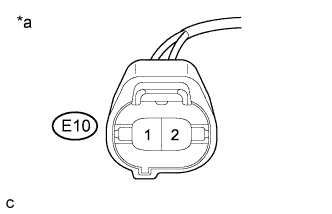
Text in Illustration *a Front view of wire harness connector
(to Duty Vacuum Switching Valve (for Active Control Engine Mount))
Disconnect the duty vacuum switching valve (for active control engine mount) connector.
-
Turn the engine switch on (IG).
-
Measure the voltage according to the value(s) in the table below.
Standard Voltage Tester Connection Switch Condition Specified Condition E10-1 - Body ground Engine switch on (IG) 11 to 14 V
NG 
CHECK HARNESS AND CONNECTOR (DUTY VACUUM SWITCHING VALVE (FOR ACTIVE CONTROL ENGINE MOUNT) - NO. 1 INTEGRATION RELAY) Click here
OK
-
-
CHECK HARNESS AND CONNECTOR (DUTY VACUUM SWITCHING VALVE (FOR ACTIVE CONTROL ENGINE MOUNT) - ECM)
-
Disconnect the duty vacuum switching valve (for active control engine mount) connector.
-
Disconnect the ECM connector.
-
Measure the resistance according to the value(s) in the table below.
Standard Resistance Tester Connection Condition Specified Condition E10-2 - A25-8 (ACM) Always Below 1 Ω E10-2 or A25-8 (ACM) - Body ground Always 10 kΩ or higher
NG
REPAIR OR REPLACE HARNESS OR CONNECTOR
OK 
REPLACE ECM Click here
-
-
CHECK HARNESS AND CONNECTOR (DUTY VACUUM SWITCHING VALVE (FOR ACTIVE CONTROL ENGINE MOUNT) - NO. 1 INTEGRATION RELAY)
-
Disconnect the duty vacuum switching valve (for active control engine mount) connector.
-
Remove the No. 1 integration relay from the engine room relay block and junction block assembly.
-
Measure the resistance according to the value(s) in the table below.
Standard Resistance Tester Connection Condition Specified Condition E10-1 - 1A-8 Always Below 1 Ω E10-1 or 1A-8 - Body ground Always 10 kΩ or higher
NG
REPAIR OR REPLACE HARNESS OR CONNECTOR
OK
GO TO ECM POWER SOURCE CIRCUIT Click here
-