SFI SYSTEM, Diagnostic DTC:P2121

| DTC Code | DTC Name |
|---|---|
| P2121 | Throttle / Pedal Position Sensor / Switch "D" Circuit Range / Performance |
DESCRIPTION
Tech Tips
This DTC relates to the accelerator pedal position sensor.
Refer to DTC P2120 Click here.
| DTC No. | DTC Detection Condition | Trouble Area |
|---|---|---|
| P2121 | Either of following conditions 1 or 2 met for 0.5 seconds (1 trip detection logic):
|
|
MONITOR DESCRIPTION
The accelerator pedal position sensor is mounted on the accelerator pedal bracket. The accelerator pedal position sensor has 2 sensor elements and 2 signal outputs: VPA and VPA2. VPA is used to detect the actual accelerator pedal angle (used for engine control) and VPA2 is used to detect malfunctions in VPA. When the difference between the output voltages of VPA and VPA2 deviates from the standard, the ECM determines that the accelerator pedal position sensor is malfunctioning. The ECM illuminates the MIL and stores the DTC.
MONITOR STRATEGY
| Related DTCs | P2121: Accelerator pedal position sensor rationality |
| Required Sensors/Components (Main) | Accelerator pedal sensor assembly |
| Required Sensors/Components (Related) | - |
| Frequency of Operation | Continuous |
| Duration | -: Case 1 0.5 seconds: Case 2 |
| MIL Operation | Immediate |
| Sequence of Operation | None |
TYPICAL ENABLING CONDITIONS
| Monitor runs whenever following DTCs not stored | None |
| Either of the following conditions met | 1 or 2 |
| 1. Engine switch | On (IG) |
| 2. Command to electronic throttle actuator power | On |
| Accelerator pedal position sensor circuit fail (P2120, P2122, P2123, P2125, P2127, P2128, P2138) | Not detected |
TYPICAL MALFUNCTION THRESHOLDS
| Difference between VPA voltage and VPA2 voltage (learned value of accelerator off position) | Less than 0.4 V, or higher than 1.2 V |
| All of the following conditions are met | - |
| [(VPA voltage - Learned VPA accelerator off position voltage) - (VPA2 voltage - Learned VPA2 accelerator off position voltage)] | 0.165 V or higher (varies with accelerator position) |
| VPA2 voltage | Less than 4.84 V |
| Either of the following conditions met | a or b |
| a) VPA voltage - Learned VPA accelerator off position | 0.04 V or higher |
| b) VPA2 voltage - Learned VPA2 accelerator off position voltage | 0.04 V or higher |
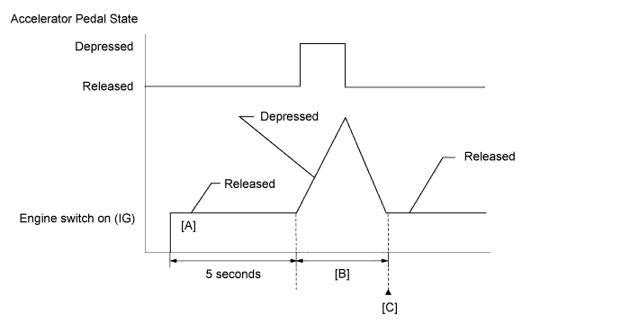
CONFIRMATION DRIVING PATTERN
-
Connect the Techstream to the DLC3.
-
Turn the engine switch on (IG) and turn the Techstream on.
-
Clear the DTCs (even if no DTCs are stored, perform the clear DTC procedure).
-
Turn the engine switch off and wait for at least 30 seconds.
-
Turn the engine switch on (IG) and turn the Techstream on [A].
-
Wait for 5 seconds after turning the engine switch on (IG).
-
Operate the accelerator pedal in accordance with the following procedure [B].
-
Enter the following menus: Powertrain / Engine / Data List / Gas Throttle / Accel Sens. No. 1 Volt %, and Accel Sens. No. 2 Volt %.
-
Slowly depress the accelerator pedal until Accel Sens. No. 1 Volt % is approximately 30% and Accel Sens. No. 2 Volt % is approximately 46%, then slowly release the accelerator pedal.
-
Enter the following menus: Powertrain / Engine / Trouble Codes [C].
-
Read the pending DTCs.
Tech Tips
-
If a pending DTC is output, the system is malfunctioning.
-
If a pending DTC is not output, perform the following procedure.
-
-
Enter the following menus: Powertrain / Engine / Utility / All Readiness.
-
Input the DTC: P2121.
-
Check the DTC judgment result.
Techstream Display Description NORMAL
-
DTC judgment completed
-
System normal
ABNORMAL
-
DTC judgment completed
-
System abnormal
INCOMPLETE
-
DTC judgment not completed
-
Perform driving pattern after confirming DTC enabling conditions
N/A
-
Unable to perform DTC judgment
-
Number of DTCs which do not fulfill DTC preconditions has reached ECU memory limit
Tech Tips
-
If the judgment result shows NORMAL, the system is normal.
-
If the judgment result shows ABNORMAL, the system has a malfunction.
-
If the judgment result shows INCOMPLETE or N/A, perform steps [B] and [C] again.
-
-
If no pending DTC is output, perform a universal trip and check for permanent DTCs Click here.
Tech Tips
-
If a permanent DTC is output, the system is malfunctioning.
-
If no permanent DTC is output, the system is normal.
-
FAIL-SAFE
The accelerator pedal sensor assembly has 2 (main and sub) sensor circuits. If a malfunction occurs in either of the sensor circuits, the ECM limits the engine output. If both circuits malfunction, the ECM regards of the accelerator pedal angle as being fully closed. In this case, the throttle valve remains closed as if the engine is idling.
If a pass condition is detected and then the engine switch is turned off, the fail-safe operation stops and the system returns to normal.
WIRING DIAGRAM
Refer to DTC P2120 Click here.
INSPECTION PROCEDURE
Tech Tips
Read freeze frame data using the Techstream. The ECM records vehicle and driving condition information as freeze frame data the moment a DTC is stored. When troubleshooting, freeze frame data can help determine if the vehicle was moving or stationary, if the engine was warmed up or not, if the air fuel ratio was lean or rich, and other data from the time the malfunction occurred.
PROCEDURE
-
CHECK ANY OTHER DTCS OUTPUT (IN ADDITION TO DTC P2121)
-
Connect the Techstream to the DLC3.
-
Turn the engine switch on (IG).
-
Turn the Techstream on.
-
Enter the following menus: Powertrain / Engine / Trouble Codes.
-
Read the DTCs.
Result Result Proceed to DTC P2121 is output A DTC P2121 and other DTCs are output B Tech Tips
If any DTCs other than P2121 are output, troubleshoot those DTCs first.
B 
GO TO DTC CHART Click here
A 
-
-
READ VALUE USING TECHSTREAM (ACCEL SENSOR OUT)
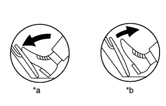
Text in Illustration *a Fully Depressed *b Fully Released
-
Connect the Techstream to the DLC3.
-
Turn the engine switch on (IG).
-
Turn the Techstream on.
-
Enter the following menus: Powertrain / Engine / Data List / Gas Throttle / Accel Sensor Out No. 1 and Accel Sensor Out No. 2.
-
Read the values displayed on the Techstream.
Standard Voltage Accelerator Pedal Operation Accel Sensor Out No. 1 Accel Sensor Out No. 2 Fully Released 0.5 to 1.1 V 1.2 to 2.0 V Fully Depressed 2.6 to 4.5 V 3.4 to 4.75 V
NG 
REPLACE ACCELERATOR PEDAL SENSOR ASSEMBLY Click here
OK 
CHECK FOR INTERMITTENT PROBLEMS Click here
-
-
REPLACE ACCELERATOR PEDAL SENSOR ASSEMBLY
-
Replace the accelerator pedal sensor assembly Click here.
NEXT
-
-
CHECK WHETHER DTC OUTPUT RECURS (DTC P2121)
-
Connect the Techstream to the DLC3.
-
Turn the engine switch on (IG).
-
Turn the Techstream on.
-
Clear the DTCs Click here.
-
Turn the engine switch off and wait for at least 30 seconds.
-
Turn the engine switch on (IG) and turn the Techstream on.
-
Drive the vehicle in accordance with the driving pattern described in Confirmation Driving Pattern.
-
Enter the following menus: Powertrain / Engine / Trouble Codes.
-
Read the DTCs.
Result Result Proceed to DTC P2121 is output A DTC is not output B
B
END
A
REPLACE ECM Click here
-