SFI SYSTEM, Diagnostic DTC:P0441

| DTC Code | DTC Name |
|---|---|
| P0441 | Evaporative Emission Control System Incorrect Purge Flow |
DTC SUMMARY
| DTC No. | Monitoring Item | Malfunction Detection Condition | Trouble Area | Detection Timing | Detection Logic |
|---|---|---|---|---|---|
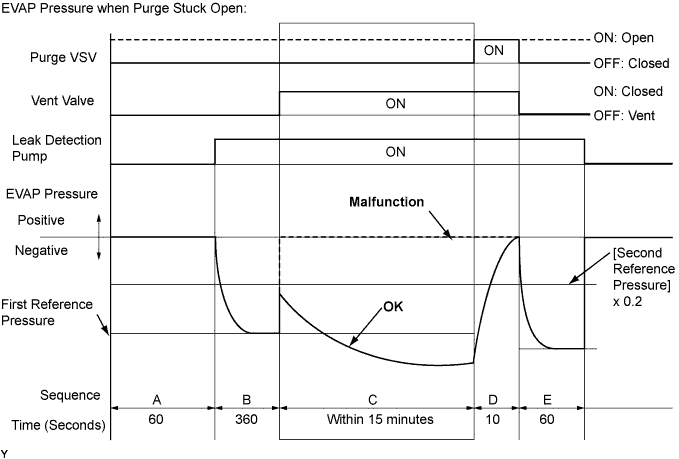
| P0441 | Purge VSV (Vacuum Switching Valve) stuck open | Leak detection pump creates negative pressure (vacuum) in EVAP system and EVAP system pressure measured. Reference pressure is measured at start and at end of leak check. If stabilized pressure higher than [second reference pressure x 0.2], ECM determines that purge VSV stuck open. |
|
While ignition switch off | 2 trip |
| Purge VSV stuck closed | After EVAP leak check performed, purge VSV turned on (open), and atmospheric air introduced into EVAP system. Reference pressure is measured at start and at end of check. If pressure does not return to near atmospheric pressure, ECM determines that purge VSV stuck closed. |
|
While ignition switch off | 2 trip | |
| Purge flow | While engine running, following conditions successively met:
|
|
While engine running | 2 trip |
DESCRIPTION
The description can be found in EVAP (Evaporative Emission) System Click here.
MONITOR DESCRIPTION
The 2 monitors, Key-off and purge flow, are used to detect malfunctions relating to DTC P0441. The Key-off monitor is initiated by the ECM internal timer, known as the soak timer, 5 hours after the ignition switch is turned off. The purge flow monitor runs while the engine is running.
-
KEY-OFF MONITOR
5 hours* after the ignition switch is turned off, the electric leak detection pump creates negative pressure (vacuum) in the EVAP (Evaporative Emission) system. The ECM monitors for leaks and actuator malfunctions based on the EVAP pressure.
Tech Tips
*: If the engine coolant temperature is not below 35°C (95°F) 5 hours after the ignition switch is turned off, the monitor check starts 2 hours later. If it is still not below 35°C (95°F) 7 hours after the ignition switch is turned off, the monitor check starts 2.5 hours later.
Sequence Operation Description Duration - ECM activation Activated by soak timer 5, 7 or 9.5 hours after ignition switch turned off. - A Atmospheric pressure measurement Vent valve is turned off (vent) and EVAP system pressure is measured by ECM in order to register atmospheric pressure.
If pressure in EVAP system is not between 70 kPa(abs) and 110 kPa(abs) [525 mmHg(abs) and 825 mmHg(abs)], ECM cancels EVAP system monitor.
60 seconds B First reference pressure measurement In order to determine reference pressure, leak detection pump creates negative pressure (vacuum) through reference orifice and then ECM checks if leak detection pump and vent valve operate normally. 360 seconds C EVAP system pressure measurement Vent valve is turned on (closed) to shut EVAP system.
Negative pressure (vacuum) is created in EVAP system, and EVAP system pressure is then measured.
Write down measured value as it will be used in leak check.
If EVAP pressure does not stabilize within 15 minutes, ECM cancels EVAP system monitor.
15 minutes* D Purge VSV monitor Purge VSV opened and then EVAP system pressure is measured by ECM.
A large increase indicates normality.
10 seconds E Second reference pressure measurement After second reference pressure measurement, leak check is performed by comparing first and second reference pressure measurements.
If stabilized system pressure is higher than second reference pressure, ECM determines that EVAP system leaking.
60 seconds - Final check Atmospheric pressure is measured and then monitoring result is recorded by ECM. - *: If only a small amount of fuel is in the fuel tank, it takes longer for the EVAP pressure to stabilize.
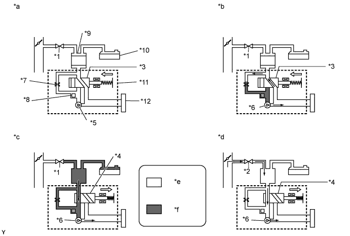
Text in Illustration *1 Purge VSV: Off (Closed) *2 Purge VSV: On (Open) *3 Vent Valve: Off (Vent) *4 Vent Valve: On (Closed) *5 Leak Detection Pump: Off *6 Leak Detection Pump: On *7 Reference Orifice (0.02 inch) *8 Canister Pressure Sensor *9 Canister *10 Fuel Tank *11 Canister Pump Module *12 Canister Filter *a Operation A:
Atmospheric Pressure Measurement
*b Operation B, E:
Reference Pressure Measurement
*c Operation C:
EVAP System Pressure Measurement
*d Operation D:
Purge VSV Monitor
*e Atmospheric Pressure *f Negative Pressure -
Purge VSV stuck open
In operation C, the leak detection pump creates negative pressure (vacuum) in the EVAP (Evaporative Emission) system. The EVAP system pressure is then measured by the ECM using the canister pressure sensor. If the stabilized system pressure is higher than [second reference pressure x 0.2], the ECM interprets this as the purge VSV being stuck open. The ECM illuminates the MIL and stores the DTC (2 trip detection logic).
-
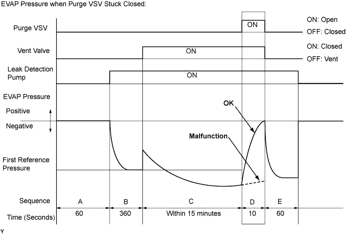
Purge VSV stuck closed
In operation D, the canister pressure sensor measures the EVAP (Evaporative Emission) system pressure. The pressure measurement for the purge VSV monitor begins when the purge VSV is turned on (open) after the EVAP leak check. When the measured pressure indicates an increase of 0.3 kPa(gauge) [2.25 mmHg(gauge)] or higher, the purge VSV is functioning normally. If the pressure does not increase, the ECM interprets this as the purge VSV being stuck closed, illuminates the MIL and stores the DTC (2 trip detection logic).
-
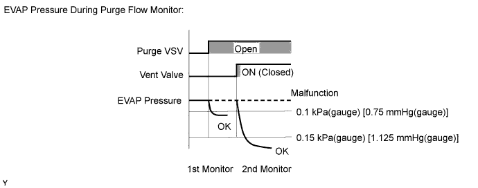
PURGE FLOW MONITOR
The purge flow monitor consists of 2 monitors. The 1st monitor is conducted every time and the 2nd monitor is activated if necessary.
-
The 1st monitor
While the engine is running and the purge VSV is on (open), the ECM monitors the purge flow by measuring the EVAP pressure change. If negative pressure is not created, the ECM begins the 2nd monitor.
-
The 2nd monitor
The vent valve is turned on (closed) and the EVAP pressure is then measured. If the variation in the pressure is less than 0.15 kPa(gauge) [1.125 mmHg(gauge)], the ECM interprets this as the purge VSV being stuck closed, illuminates the MIL and stores DTC P0441 (2 trip detection logic).
Atmospheric pressure check:
In order to ensure reliable malfunction detection, the variation between the atmospheric pressures, before and after conduction of the purge flow monitor, is measured by the ECM.
MONITOR STRATEGY
| Required Sensors/Components (Main) | Purge VSV Canister pump module |
| Required Sensors/Components (Related) | - |
| Frequency of Operation | Once per driving cycle |
| Duration | Within 20 minutes: Purge VSV stuck open/close Within 30 seconds: Purge flow |
| MIL Operation | 2 driving cycles |
| Sequence of Operation | None |
TYPICAL ENABLING CONDITIONS
| Monitor runs whenever the following DTCs are not stored | None |
| Atmospheric pressure | 70 kPa(abs) [525 mmHg(abs)] or higher, and less than 110 kPa(abs) [825 mmHg(abs)] |
| Battery voltage | 10.5 V or higher |
| Vehicle speed | Less than 4 km/h (2.5 mph) |
| Ignition switch | Off |
| Time after key-off | 5, 7 or 9.5 hours |
| Canister pressure sensor malfunction (P0452, P0453) | Not detected |
| Purge VSV | Not operated by scan tool |
| Vent valve | Not operated by scan tool |
| Leak detection pump | Not operated by scan tool |
| Both of following conditions met before key-off | Conditions 1 and 2 |
| 1. Duration that vehicle is driven | 5 minutes or more |
| 2. EVAP purge operation | Performed |
| Engine coolant temperature | 4.4°C (40°F) or higher, and less than 35°C (95°F) |
| Intake air temperature | 4.4°C (40°F) or higher, and less than 35°C (95°F) |
| Engine | Running |
| Engine coolant temperature | 4.4°C (40°F) or higher |
| Intake air temperature | 4.4°C (40°F) or higher |
| Canister pressure sensor malfunction | Not detected |
| Purge VSV | Not operated by scan tool |
| EVAP system check | Not operated by scan tool |
| Atmospheric pressure | 75 kPa(abs) [562 mmHg(abs)] or higher, and less than 110 kPa(abs) [825 mmHg(abs)] |
| Battery voltage | 10 V or higher (intake air temperature below 50°C (122°F)) or 12 V or higher (intake air temperature below 50°C (122°F)) or higher |
| Purge duty-cycle | 8% or higher |
TYPICAL MALFUNCTION THRESHOLDS
| EVAP pressure when vacuum introduction is complete | Higher than [reference pressure x 0.2] |
| EVAP pressure change after purge VSV is open | Less than 0.3 kPa(gauge) [2.25 mmHg(gauge)] |
| Both of the following conditions are met: | Conditions 1 and 2 |
| 1. EVAP pressure change when purge flow is started | Less than 0.1 kPa(gauge) [0.75 mmHg(gauge)] |
| 2. EVAP pressure change during purge operation when vent valve closed | Less than 0.15 kPa(gauge) [1.125 mmHg(gauge)] |
MONITOR RESULT
Refer to EVAP system Click here.
CONFIRMATION DRIVING PATTERN
The vehicle has Evaporative System Check.-
Connect the Techstream to the DLC3.
-
Turn the ignition switch to ON and turn the Techstream on.
-
Clear the DTCs (even if no DTCs are stored, perform the clear DTC procedure).
-
Turn the ignition switch off and wait for at least 30 seconds.
-
Turn the ignition switch to ON and turn the Techstream on.
-
Start the engine and wait 15 minutes or more.
-
Enter the following menus: Powertrain / Engine and ECT / Trouble Codes.
-
Read the pending DTCs.
Tech Tips
-
If a pending DTC is output, the system is malfunctioning.
-
If a pending DTC is not output, perform the following procedure.
-
-
Enter the following menus: Powertrain / Engine and ECT / Utility / All Readiness.
-
Input the DTC: P0441.
-
Check the DTC judgment result.
Techstream Display Description NORMAL
-
DTC judgment completed
-
System normal
ABNORMAL
-
DTC judgment completed
-
System abnormal
INCOMPLETE
-
DTC judgment not completed
-
You should perform driving pattern after confirming DTC enabling conditions
N/A
-
Unable to perform DTC judgment
-
Number of DTCs which do not fulfill DTC preconditions has reached ECU memory limit
Tech Tips
-
If the judgment result shows NORMAL, the system is normal.
-
If the judgment result shows ABNORMAL, the system has a malfunction.
-
If the judgment result shows INCOMPLETE or N/A, perform the following procedure.
Note
-
The Evaporative System Check (Automatic Mode) consists of 6 steps performed automatically by the Techstream. It takes a maximum of approximately 24 minutes.
-
Do not perform the Evaporative System Check when the fuel tank is higher than 90% full because the cut-off valve may be closed, making the fuel tank leak check unavailable.
-
Do not run the engine during this operation.
-
When the temperature of the fuel is 35°C (95°F) or higher, a large amount of vapor forms and any check results become inaccurate. When performing the Evaporative System Check, keep the fuel temperature below 35°C (95°F).
-
-
Clear the DTCs (even if no DTCs are stored, perform the clear DTC procedure).
-
Turn the ignition switch off and wait for at least 30 seconds.
-
Turn the ignition switch to ON and turn the Techstream on.
-
Enter the following menus: Powertrain / Engine and ECT / Utility / Evaporative System Check / Automatic Mode.
-
After the Evaporative System Check is completed, check for All Readiness by entering the following menus: Powertrain / Engine and ECT / Utility / All Readiness.
-
Input the DTC: P0441.
-
Check the DTC judgment result.
Techstream Display Description NORMAL
-
DTC judgment completed
-
System normal
ABNORMAL
-
DTC judgment completed
-
System abnormal
INCOMPLETE
-
DTC judgment not completed
-
Perform driving pattern after confirming DTC enabling conditions
N/A
-
Unable to perform DTC judgment
-
Number of DTCs which do not fulfill DTC preconditions has reached ECU memory limit
Tech Tips
-
If the judgment result shows NORMAL, the system is normal.
-
If the judgment result shows ABNORMAL, the system has a malfunction.
-
-
If the judgment result is INCOMPLETE or N/A and no pending DTC is output, perform a universal trip and check for permanent DTCs Click here.
Tech Tips
-
If a permanent DTC is output, the system is malfunctioning.
-
If no permanent DTC is output, the system is normal.
-
-
Connect the Techstream to the DLC3.
-
Turn the ignition switch to ON and turn the Techstream on.
-
Clear the DTCs (even if no DTCs are stored, perform the clear DTC procedure).
-
Turn the ignition switch off and wait for at least 30 seconds.
-
Turn the ignition switch to ON and turn the Techstream on.
-
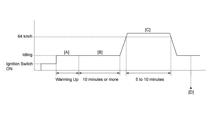
Start the engine and warm it up until the engine coolant temperature reaches 75°C (167°F) or higher [A].
-
Idle the engine for 10 minutes or more [B].
-
Drive the vehicle at 64 km/h (40 mph) for 5 to 10 minutes [C].
CAUTION:
When performing the confirmation driving pattern, obey all speed limits and traffic laws.
-
Enter the following menus: Powertrain / Engine and ECT / Trouble Codes.
-
Read the pending DTCs [D].
Tech Tips
-
If a pending DTC is output, the system is malfunctioning.
-
If a pending DTC is not output, perform the following procedure.
-
-
Enter the following menus: Powertrain / Engine and ECT / Utility / All Readiness.
-
Input the DTC: P0441.
-
Check the DTC judgment result.
Techstream Display Description NORMAL
-
DTC judgment completed
-
System normal
ABNORMAL
-
DTC judgment completed
-
System abnormal
INCOMPLETE
-
DTC judgment not completed
-
Perform driving pattern after confirming DTC enabling conditions
N/A
-
Unable to perform DTC judgment
-
Number of DTCs which do not fulfill DTC preconditions has reached ECU memory limit
Tech Tips
-
If the judgment result shows NORMAL, the system is normal.
-
If the judgment result shows ABNORMAL, the system has a malfunction.
-
If the judgment result shows INCOMPLETE or N/A, perform the steps [B] through [D].
-
-
If no pending DTC is output, perform a universal trip and check for permanent DTCs Click here.
Tech Tips
-
If a permanent DTC is output, the system is malfunctioning.
-
If no permanent DTC is output, the system is normal.
-
WIRING DIAGRAM
Refer to DTC P0451 Click here.
INSPECTION PROCEDURE
PROCEDURE
-
CHECK IF VEHICLE IS EQUIPPED WITH EVAPORATIVE SYSTEM CHECK
-
Connect the Techstream to the DLC3.
-
Turn the ignition switch to ON.
-
Turn the Techstream on.
-
Enter the following menus: Powertrain / Engine and ECT / Utility.
-
Check whether the vehicle is equipped with Evaporative System Check.
Result Result Proceed to The vehicle does not have Evaporative System Check A The vehicle has Evaporative System Check B
B 
GO TO EVAP SYSTEM Click here
A 
-
-
PERFORM ACTIVE TEST USING TECHSTREAM (PURGE VSV)
-
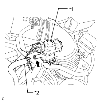
Text in Illustration *1 Purge VSV *2 Fuel Vapor Feed Hose (to Canister) Disconnect the fuel vapor feed hose (connected to the canister) from the purge VSV.
-
Connect the Techstream to the DLC3.
-
Start the engine.
-
Turn the Techstream on.
-
Enter the following menus: Powertrain / Engine and ECT / Active Test / Activate the VSV for Evap Control.
-
Using the Techstream, turn off the purge VSV (Activate the VSV for Evap Control: OFF).
-
Use your finger to confirm that the purge VSV has no suction.
-
Using the Techstream, turn on the purge VSV (Activate the VSV for Evap Control: ON).
-
Use your finger to confirm that the purge VSV has suction.
Result Result Proceed to Suction when purge VSV turned on A No suction when purge VSV turned on B
NG 
CHECK EVAP PURGE LINE (PURGE VSV - INTAKE MANIFOLD) Click here
OK
-
-
CHECK FUEL TANK CAP ASSEMBLY
-
Check that the fuel tank cap is correctly installed and confirm that the fuel tank cap meets OEM specifications.
-
Tighten the fuel tank cap firmly (only one click sound could be heard).
OK A normal fuel tank cap assembly is properly installed. Tech Tips
If an EVAP tester is available, check the fuel tank cap using the EVAP tester.
-
Remove the fuel tank cap and install it onto a fuel tank cap adapter.
-
Connect an EVAP tester pump hose to the adapter, and pressurize the cap to 3.2 to 3.7 kPa(gauge) [24 to 28 mmHg(gauge)] using an EVAP tester pump.
-
Seal the adapter and wait for 2 minutes.
-
Check the pressure. If the pressure is 2 kPa(gauge) [15 mmHg(gauge)] or more, the fuel tank cap is normal.
-
NG
REPLACE FUEL TANK CAP ASSEMBLY
OK
-
-
CHECK EVAP PURGE LINE (PURGE VSV - CHARCOAL CANISTER ASSEMBLY)
-
Check for blockages or leakages in the EVAP purge line between the purge VSV and canister.
OK No blockages and leakages in the EVAP purge line between the purge VSV and canister.
NG
REPAIR OR REPLACE EVAP PURGE LINE (PURGE VSV - CANISTER ASSEMBLY)
OK
-
-
INSPECT CHARCOAL CANISTER ASSEMBLY (CHARCOAL FILTER INSIDE CANISTER)
-
Check for filter blockage in the canister Click here.
OK No blockages in the canister.
NG
REPLACE CHARCOAL CANISTER ASSEMBLY Click here
OK
-
-
FOUND EVAP LEAK PART
-
Disconnect the vent hose.
-
Connect the EVAP pressure tester tool to the canister pump module with the adapter.
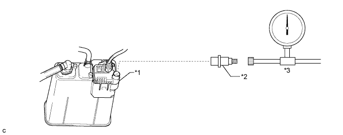
Text in Illustration *1 Canister Pump Module *2 Adapter *3 EVAP Pressure Tester Tool - - -
Pressurize the EVAP system to 3.2 to 3.7 kPa(gauge) [24 to 28 mmHg(gauge)].
-
Apply soapy water to the piping and connecting parts of the EVAP system.
-
Look for areas where bubbles appear. This indicates the leak point.
OK No leaks in EVAP system. Tech Tips
Disconnect the hose between the canister and fuel tank from the canister. Block the canister side and conduct an inspection. In this way, the fuel tank can be excluded as an area suspected of causing fuel leaks.
NG
REPAIR OR REPLACE EVAP LEAK PART
OK
-
-
CHECK HARNESS AND CONNECTOR (CANISTER PUMP MODULE - ECM, POWER SOURCE)
-
Disconnect the canister pump module connector.
-
Disconnect the ECM connector.
-
Disconnect the No. 1 integration relay connector.
-
Measure the resistance according to the value(s) in the table below.
Standard Resistance Tester Connection Condition Specified Condition N35-1 (VGND) - A25-7 (VPMP) Always Below 1 Ω N35-5 (VLVB) - 1C-4 Always Below 1 Ω N35-1 (VGND) or A25-7 (VPMP) - Body ground Always 10 kΩ or higher N35-5 (VLVB) or 1C-4 - Body ground Always 10 kΩ or higher
NG
REPAIR OR REPLACE HARNESS OR CONNECTOR
OK
-
-
REPLACE CANISTER PUMP MODULE
-
Replace the canister pump module Click here.
Note
-
When replacing the canister pump module, check the canister pump module interior, canister interior and related pipes for water, fuel and other liquids. If liquids are present, check for disconnections and/or cracks in the following: 1) the pipe from the air inlet port to the canister pump module; 2) the canister filter; and 3) the fuel tank vent hose. If liquids are present in the canister interior, replace canister and canister pump module together.
-
Check for filter blockage in the canister. If the charcoal filter inside the canister is clogged, replace the canister and canister pump module together.
-
Check for filter blockage in the canister filter. If the canister filter has blockages, replace the canister filter.
-
-
Connect the EVAP pressure tester tool to the canister pump module with the adapter.
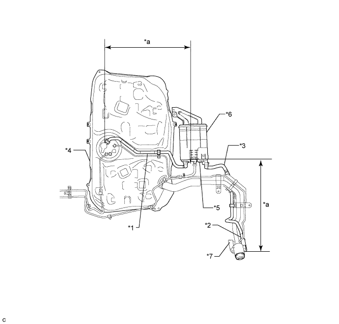
Text in Illustration *1 Fuel Tank Vent Hose *2 Air Inlet Port *3 Vent Hose *4 Fuel Tank *5 Canister Pump Module *6 Canister *7 Canister Filter - - *a Inspection Area
(check for disconnection and/or cracks)
- -
NEXT
-
-
CHECK WHETHER DTC OUTPUT RECURS (AFTER REPAIR)
-
Connect the Techstream to the DLC3.
-
Turn the ignition switch to ON.
-
Turn the Techstream on.
-
Clear the DTCs.
-
Turn the ignition switch off and wait for at least 30 seconds.
-
Turn the ignition switch to ON.
-
Turn the Techstream on.
-
Start the engine and warm it up.
-
Drive the vehicle in accordance with the driving pattern described in Confirmation Driving Pattern.
-
Enter the following menus: Powertrain / Engine and ECT / Trouble Codes.
-
Read the DTCs.
Result Result Proceed to DTC is not output A DTC P0441 is output B
B
REPLACE ECM Click here
A 
END
-
-
CHECK EVAP PURGE LINE (PURGE VSV - INTAKE MANIFOLD)
-
Check for blockages or leakages in the EVAP purge line between the purge VSV and intake manifold.
OK No blockages and leakages in the EVAP purge line between the purge VSV and intake manifold.
NG
INSPECT INTAKE MANIFOLD (EVAP PURGE PORT) Click here
OK
-
-
INSPECT PURGE VSV
-
Inspect the purge VSV Click here.
NG
REPLACE PURGE VSV Click here
OK
-
-
CHECK TERMINAL VOLTAGE (POWER SOURCE OF PURGE VSV)
-
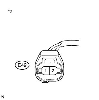
Text in Illustration *a Front view of wire harness connector
(to Purge VSV)
Disconnect the purge VSV connector.
-
Turn the ignition switch to ON.
-
Measure the voltage according to the value(s) in the table below.
Standard Voltage Tester Connection Condition Specified Condition E49-1 - Body ground Ignition switch ON 11 to 14 V
NG
REPAIR OR REPLACE HARNESS OR CONNECTOR (PURGE VSV - NO. 1 INTEGRATION RELAY)
OK
-
-
CHECK HARNESS AND CONNECTOR (PURGE VSV - ECM)
-
Disconnect the purge VSV connector.
-
Disconnect the ECM connector.
-
Measure the resistance according to the value(s) in the table below.
Standard Resistance Tester Connection Condition Specified Condition E49-2 - E26-68 (PRG) Always Below 1 Ω E49-2 or E26-68 (PRG) - Body ground Always 10 kΩ or higher
NG
REPAIR OR REPLACE HARNESS OR CONNECTOR
OK
END
-
-
INSPECT INTAKE MANIFOLD (EVAP PURGE PORT)
-
Disconnect the EVAP hose from the intake manifold.
-
Start the engine and warm it up.
-
Use your finger to confirm that the port of the intake manifold has suction.
Result Result Proceed to Suction applied A No suction B
B
REPLACE INTAKE MANIFOLD Click here
A
REPAIR OR REPLACE EVAP PURGE LINE (PURGE VSV - INTAKE MANIFOLD)
-