SFI SYSTEM, Diagnostic DTC:P0111

| DTC Code | DTC Name |
|---|---|
| P0111 | Intake Air Temperature Sensor Gradient Too High |
DESCRIPTION
-
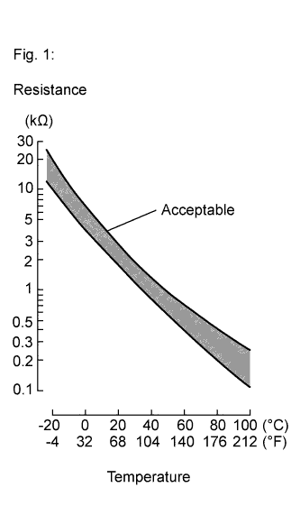
The intake air temperature sensor, mounted on the mass air flow meter sub-assembly, monitors the intake air temperature. The intake air temperature sensor has a built-in thermistor with a resistance that varies according to the temperature of the intake air. When the intake air temperature is low, the resistance of the thermistor increases. When the temperature is high, the resistance drops. These variations in resistance are transmitted to the ECM as voltage changes (See Fig. 1).
-
The intake air temperature sensor is powered by a 5 V supply from the THA terminal of the ECM, via resistor R.
-
Resistor R and the intake air temperature sensor are connected in series. When the resistance value of the intake air temperature sensor changes, according to changes in the intake air temperature, the voltage at terminal THA also varies. Based on this signal, the ECM increases the fuel injection volume when the engine is cold to improve driveability.
| DTC No. | DTC Detection Condition | Trouble Area |
|---|---|---|
| P0111 | Either of the following condition is met (2 trip detection logic).
|
Mass air flow meter sub-assembly |
MONITOR DESCRIPTION
The ECM performs OBD II monitoring based on the values from the intake air temperature sensor. If there is no change of the sensor value within the normal range, the ECM will not be able to perform OBD II monitoring or will misdiagnose that there is a malfunction in the sensor. The ECM detects when the intake air temperature sensor value is stuck by performing monitoring after the ignition switch is turned off or the engine is started (short soak or long soak).
MONITOR STRATEGY
| Related DTCs | P0111: Intake air temperature sensor rationality (after engine stop) P0111: Intake air temperature sensor rationality (after cold engine start) |
| Required Sensors/Components (Main) | Intake air temperature sensor |
| Required Sensors/Components (Related) | - |
| Frequency of Operation | Once per driving cycle |
| Duration | - |
| MIL Operation | 2 driving cycles |
| Sequence of Operation | None |
TYPICAL ENABLING CONDITIONS
| Monitor runs whenever the following DTCs are not stored | None |
| All of the following conditions are met | - |
| Time after engine start | 10 seconds or more |
| Battery voltage | 10.5 V or higher |
| Engine coolant temperature at ECM started by internal engine off timer | -40°C (-40°F) or higher |
| Engine coolant temperature before engine stop | 70°C (158°F) or higher |
| Time that mass air flow is low before engine stop | 2100 seconds or more |
| Accumulated mass air flow amount before engine stop | 2207 g or more |
| Key-off duration | 30 minutes |
| Mass air flow meter circuit fail (P0102, P0103) | Not detected |
| Engine coolant temperature sensor circuit fail (P0115, P0117, P0118) | Not detected |
| Intake air temperature sensor circuit fail (P0112, P0113) | Not detected |
| Soak timer fail (P2610) | Not detected |
| All of the following conditions are met | - |
| Key-off duration | 5 hours or more |
| Time after engine start | 10 seconds or more |
| Engine coolant temperature | 70°C (158°F) or higher |
| Accumulated mass air flow amount | 2207 g or more |
| Either of the following conditions is met | 1 or 2 |
| 1. Duration while engine load is low | 120 seconds or more |
| 2. Duration while engine load is high | 10 seconds or more |
| Mass air flow meter circuit fail (P0102, P0103) | Not detected |
| Engine coolant temperature sensor circuit fail (P0115, P0117, P0118) | Not detected |
| Intake air temperature sensor circuit fail (P0112, P0113) | Not detected |
| Soak timer fail (P2610) | Not detected |
TYPICAL MALFUNCTION THRESHOLDS
| Intake air temperature change | Less than 1°C (1.8°F) |
| Intake air temperature change | Less than 1°C (1.8°F) |
CONFIRMATION DRIVING PATTERN
-
Connect the Techstream to the DLC3.
-
Turn the ignition switch to ON and turn the Techstream on.
-
Clear the DTCs (even if no DTCs are stored, perform the clear DTC procedure).
-
Turn the ignition switch off and wait for at least 30 seconds.
-
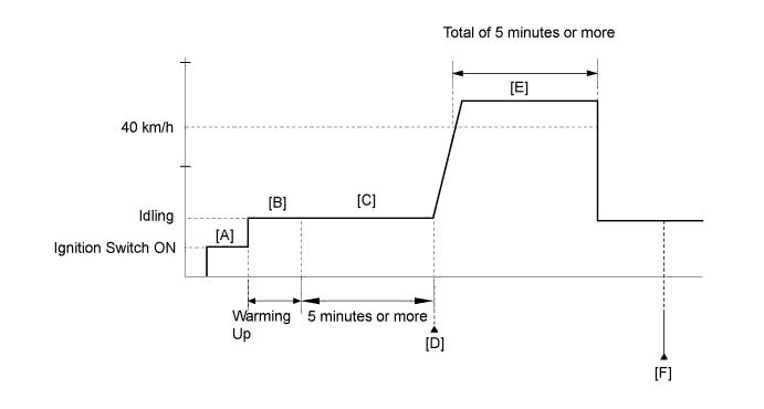
Turn the ignition switch to ON and turn the Techstream on [A].
-
Start the engine and warm it up until the engine coolant temperature reaches 75°C (167°F) or higher [B].
-
Idle the engine for 5 minutes or more [C].
Tech Tips
During steps [A] through [C], if the change in the intake air temperature is below 1°C (1.8°F), the intake air temperature sensor (mass air flow meter sub-assembly) is malfunctioning. It is not necessary to continue this procedure.
-
Enter the following menus: Powertrain / Engine and ECT / Trouble Codes [D].
-
Read the pending DTCs.
Tech Tips
-
If a pending DTC is output, the system is malfunctioning.
-
If a pending DTC is not output, perform the following procedure.
-
-
Enter the following menus: Powertrain / Engine and ECT / Utility / All Readiness.
-
Input the DTC: P0111.
-
Check the DTC judgment result.
Techstream Display Description NORMAL
-
DTC judgment completed
-
System normal
ABNORMAL
-
DTC judgment completed
-
System abnormal
INCOMPLETE
-
DTC judgment not completed
-
Perform driving pattern after confirming DTC enabling conditions
N/A
-
Unable to perform DTC judgment
-
Number of DTCs which do not fulfill DTC preconditions has reached ECU memory limit
Tech Tips
-
If the judgment result shows NORMAL, the system is normal.
-
If the judgment result shows ABNORMAL, the system has a malfunction.
-
If the judgment result shows INCOMPLETE or N/A, perform steps [E] and [F].
-
-
Drive the vehicle at 40 km/h (25 mph) or more for a total of 5 minutes or more [E].
CAUTION:
When performing the confirmation driving pattern, obey all speed limits and traffic laws.
-
Check the DTC judgment result again [F].
Tech Tips
If the judgment result shows INCOMPLETE or N/A, perform steps [E] and [F] again.
-
If no pending DTC is output, perform a universal trip and check for permanent DTCs Click here.
Tech Tips
-
If a permanent DTC is output, the system is malfunctioning.
-
If no permanent DTC is output, the system is normal.
-
WIRING DIAGRAM
Refer to DTC P0112 Click here.
INSPECTION PROCEDURE
Tech Tips
Read freeze frame data using the Techstream. The ECM records vehicle and driving condition information as freeze frame data the moment a DTC is stored. When troubleshooting, freeze frame data can help determine if the vehicle was moving or stationary, if the engine was warmed up or not, if the air fuel ratio was lean or rich, and other data from the time the malfunction occurred.
PROCEDURE
-
CHECK ANY OTHER DTCS OUTPUT (IN ADDITION TO DTC P0111)
-
Connect the Techstream to the DLC3.
-
Turn the ignition switch to ON.
-
Turn the Techstream on.
-
Enter the following menus: Powertrain / Engine and ECT / Trouble Codes.
-
Read the DTCs.
Result Result Proceed to DTC P0111 and other DTCs are output A DTC P0111 is output B Tech Tips
-
If any DTCs other than P0111 are output, troubleshoot those DTCs first.
-
Perform "Inspection After Repair" after replacing the mass air flow meter sub-assembly Click here.
-
B 
REPLACE MASS AIR FLOW METER SUB-ASSEMBLY Click here
A 
GO TO DTC CHART Click here
-