КОРПУС КЛАПАНОВ В СБОРЕ УСТАНОВКА
PROCEDURE
-
INSTALL TRANSMISSION VALVE BODY ASSEMBLY
-
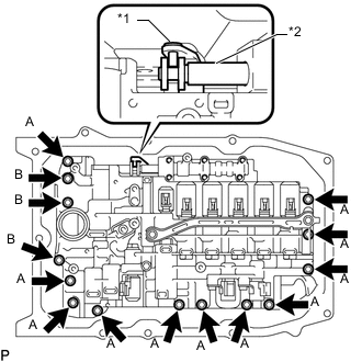
Text in Illustration *1 Manual Valve Lever Sub-assembly *2 Manual Valve Insert the manual valve lever sub-assembly into the groove on the end of the manual valve and install the transmission valve body assembly to the automatic transmission case sub-assembly with the 14 bolts.
- Torque:
- 8.0 N*m { 82 kgf*cm, 71 in.*lbf }
Bolt Length Item Specified Condition Bolt A 28 mm (1.10 in.) Bolt B 40 mm (1.57 in.) -
Mark the top of each bolt with paint.
-
Retighten the 14 bolts an additional 90°.
-
Check that the paint marks are now at a 90° angle to the top.
-
Connect the 9 connectors to the solenoid valves.
-
Connect the transmission revolution sensor (NT) connector.
-
Coat a new O-ring with the ATF and install it to the ATF temperature sensor.
-
Install the ATF temperature sensor and lock plate with the bolt.
- Torque:
- 10 N*m { 102 kgf*cm, 7 ft.*lbf }
-
-
INSTALL VALVE BODY OIL STRAINER ASSEMBLY
-
Coat a new O-ring with ATF and install it to the valve body oil strainer assembly.
Note
Ensure that the O-ring is not twisted or pinched.
-
Install the valve body oil strainer assembly to the transmission valve body assembly with the 4 bolts.
- Torque:
- 10 N*m { 102 kgf*cm, 7 ft.*lbf }
-
-
INSTALL AUTOMATIC TRANSMISSION OIL PAN SUB-ASSEMBLY
-
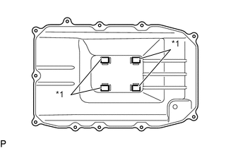
Text in Illustration *1 Transmission Oil Cleaner Magnet Install the 4 transmission oil cleaner magnets to the automatic transmission oil pan sub-assembly.
-
Install a new automatic transmission oil pan gasket and the automatic transmission oil pan sub-assembly to the automatic transmission case sub-assembly with the 11 bolts.
- Torque:
- 7.5 N*m { 76 kgf*cm, 66 in.*lbf }
Note
-
-
Make sure that there is no oil or foreign matter on the gasket seal surface and automatic transmission oil pan sub-assembly contact surface.
-
Install the gasket so that there is no slack in the gasket, and that the entire circumference of the seal surface is level.
-
Make sure that the 11 gasket drop prevention protrusions are set on the automatic transmission oil pan sub-assembly.
-
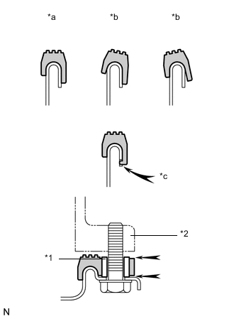
When tightening the automatic transmission oil pan sub-assembly, make sure that the gasket is not pinched between the sleeve of the gasket tightening area and the seal surface of the transmission.
Text in Illustration *1 Sleeve *2 Automatic Transmission Case Sub-assembly *a Correct *b Incorrect *c Protrusion
-
-
INSTALL OIL PAN PROTECTOR ASSEMBLY
-
INSTALL NO. 2 ENGINE UNDER COVER
-
ADD AUTOMATIC TRANSMISSION FLUID
-
RESET MEMORY