СИСТЕМА АВТОМАТИЧЕСКОЙ ТРАНСМИССИИ, Diagnostic DTC:P2716
| DTC Code | DTC Name |
|---|---|
| P2716 | Pressure Control Solenoid "D" Electrical |
DESCRIPTION
Refer to DTC P2714 Click here.
| DTC No. | DTC Detection Condition
|
Trouble Area |
|---|---|---|
| P2716 |
|
|
MONITOR DESCRIPTION
When an open or short in the shift solenoid valve SLT circuit is detected, the TCM determines that there is a malfunction. The TCM will illuminate the MIL and store this DTC.
WIRING DIAGRAM
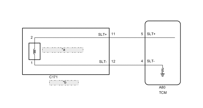
| *a | Shift Solenoid Valve SLT |
| *b | Transmission Wire |
CAUTION / NOTICE / HINT
Note
Perform registration and/or initialization when parts related to the automatic transmission are replaced Click here.
Tech Tips
After performing repair, clear the DTCs and perform the following procedure to check that DTCs are not output.
-
Perform the D Position Shift Test in Road Test Click here.
-
Check for DTCs again Click here.
PROCEDURE
-
CHECK HARNESS AND CONNECTOR (SHIFT SOLENOID VALVE SLT - TCM)
-
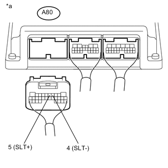
Text in Illustration *a Rear view of wire harness connector
(to TCM)
Disconnect the TCM connector.
-
Measure the resistance according to the value(s) in the table below.
Standard Resistance Tester Connection Condition Specified Condition A80-5 (SLT+) - A80-4 (SLT-) 20°C (68°F) 5.0 to 5.6 Ω A80-5 (SLT+) or A80-4 (SLT-) - Body ground Always 10 kΩ or higher
OK 
REPLACE TCM Click here
NG 
-
-
CHECK HARNESS AND CONNECTOR (TRANSMISSION WIRE - TCM)
-
Disconnect the C171 transmission wire connector.
-
Disconnect the A80 TCM connector.
-
Measure the resistance according to the value(s) in the table below.
Standard Resistance Tester Connection Condition Specified Condition C171-11 (SLT+) - A80-5 (SLT+) Always Below 1 Ω C171-12 (SLT-) - A80-4 (SLT-) Always Below 1 Ω C171-11 (SLT+) or A80-5 (SLT+) - Body ground Always 10 kΩ or higher C171-12 (SLT-) or A80-4 (SLT-) - Body ground Always 10 kΩ or higher
NG
REPAIR OR REPLACE HARNESS OR CONNECTOR
OK
-
-
INSPECT SHIFT SOLENOID VALVE SLT
-
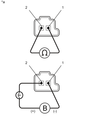
Text in Illustration *1 Shift Solenoid Valve SLT Remove the shift solenoid valve SLT Click here.
-
Measure the resistance according to the value(s) in the table below.
Standard Resistance Tester Connection Condition Specified Condition Terminal 1 of the shift solenoid valve SLT - Terminal 2 20°C (68°F) 5.0 to 5.6 Ω -
Apply 12 V battery voltage to the shift solenoid valve and check that the valve moves and makes an operating noise.
OK Measurement Condition Specified Condition
-
Battery positive (+) with a 21 W bulb → Terminal 2
-
Battery negative (-) → Terminal 1
Valve moves and makes an operating noise -
OK
REPAIR OR REPLACE TRANSMISSION WIRE Click here
NG
REPLACE SHIFT SOLENOID VALVE SLT Click here
-