СИСТЕМА АВТОМАТИЧЕСКОЙ ТРАНСМИССИИ, Diagnostic DTC:P2714
| DTC Code | DTC Name |
|---|---|
| P2714 | Pressure Control Solenoid "D" Performance or Stuck OFF |
DESCRIPTION
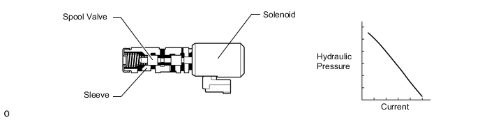
Based on signals from the accelerator position sensor and speed sensors (NT and SP2), the TCM controls the solenoid valve (SLT) using a predetermined current. As a result, the line pressure is adjusted to a pressure that is appropriate for the throttle angle and engine output. Based on the rotation speed indicated by the transmission speed sensors (NT and SP2), the TCM calculates the heat level of the friction material, and detects the slip condition of the clutch, etc.
| DTC No. | DTC Detection Condition
|
Trouble Area |
|---|---|---|
| P2714 |
|
|
MONITOR DESCRIPTION
The TCM commands gear shifts by turning the shift solenoid valves on and off. According to the input shaft speed and output shaft speed, the TCM detects the actual gear (1st, 2nd, 3rd, 4th, 5th, 6th, 7th or 8th gear position). When the gear commanded by the actual gear is not the same, the TCM illuminates the MIL* and stores this DTC.
-
*: w/ OBD
Note
If driving continues under these conditions, the clutches will burn out and the vehicle will no longer be drivable.
CAUTION / NOTICE / HINT
Note
Perform registration and/or initialization when parts related to the automatic transmission are replaced Click here.
Tech Tips
After performing repair, clear the DTCs and perform the following procedure to check that DTCs are not output.
-
Start the engine.*1
-
Drive the vehicle backward with the shift lever in R.*2
-
Turn the engine switch off.
-
Perform steps (*1) through (*2) again.
-
Check for DTCs again Click here.
PROCEDURE
-
CHECK DTC OUTPUT (IN ADDITION TO DTC P2714)
-
Connect the GTS to the DLC3.
-
Turn the engine switch on (IG).
-
Turn the GTS on.
-
Enter the following menus: Powertrain / ECT / Trouble Codes.
-
Read the DTCs using the GTS.
Result Result Proceed to DTC P2714 and DTC P0746, P076B, P076C, P0776, P0796, P08CD, P08CE, P2808 and/or P2817 are output A Only DTC P2714 is output B DTCs other than P0746, P076B, P076C, P0776, P0796, P08CD, P08CE, P2714, P2808 and P2817 are also output C Tech Tips
If DTCs other than P0746, P076B, P076C, P0776, P0796, P08CD, P08CE, P2714, P2808 and P2817 are output, perform troubleshooting for those DTCs first.
B 
INSPECT SHIFT SOLENOID VALVE SLT Click here
C 
GO TO DTC CHART Click here
A 
-
-
CLEAR DTC AND PERFORM STALL SPEED TEST
-
Clear the DTCs Click here.
Tech Tips
Write down the currently output DTCs before clearing them.
-
Perform the stall speed test Click here.
Result Test Condition Proceed to Stall speed test can be performed A Stall speed test cannot be performed B
B
INSPECT SHIFT SOLENOID VALVE SLT Click here
A
-
-
INSPECT SHIFT SOLENOID VALVE SL1, SL2, SL3, SL4 AND SL5
-
Text in Illustration *1 Shift Solenoid Valve SL1, SL2, SL3, SL4 and SL5 Remove the shift solenoid valve SL1, SL2, SL3, SL4 and SL5 Click here.
-
Measure the resistance according to the value(s) in the table below.
Standard Resistance Tester Connection Condition Specified Condition Terminal 1 of the shift solenoid valve SL1 - Terminal 2 20°C (68°F) 5.0 to 5.6 Ω Terminal 1 of the shift solenoid valve SL2 - Terminal 2 20°C (68°F) 5.0 to 5.6 Ω Terminal 1 of the shift solenoid valve SL3 - Terminal 2 20°C (68°F) 5.0 to 5.6 Ω Terminal 1 of the shift solenoid valve SL4 - Terminal 2 20°C (68°F) 5.0 to 5.6 Ω Terminal 1 of the shift solenoid valve SL5 - Terminal 2 20°C (68°F) 5.0 to 5.6 Ω -
Apply 12 V battery voltage to the shift solenoid valve and check that the valve moves and makes an operating noise.
OK Measurement Condition Specified Condition
-
Battery positive (+) with a 21 W bulb → Terminal 2
-
Battery negative (-) → Terminal 1
Valve moves and makes an operating noise -
NG
REPLACE SHIFT SOLENOID VALVE SL1, SL2, SL3, SL4 OR SL5 Click here
OK
-
-
INSPECT SHIFT SOLENOID VALVE SC2
-
Text in Illustration *1 Shift Solenoid Valve SC2 Remove the shift solenoid valve SC2 Click here.
-
Measure the resistance according to the value(s) in the table below.
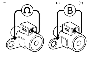
Standard Resistance Tester Connection Condition Specified Condition Terminal of shift solenoid valve SC2 connector - Shift solenoid valve SC2 body 20°C (68°F) 11 to 15 Ω -
Apply 12 V battery voltage to the shift solenoid valve and check that the valve moves and makes an operating noise.
OK Measurement Condition Specified Condition
-
Battery positive (+) → Shift solenoid valve SC2 connector
-
Battery negative (-) → Shift solenoid valve SC2 body
Valve moves and makes an operating noise -
NG
REPLACE SHIFT SOLENOID VALVE SC2 Click here
OK
-
-
INSPECT SHIFT SOLENOID VALVE SLT
-
Text in Illustration *1 Shift Solenoid Valve SLT Remove the shift solenoid valve SLT Click here.
-
Measure the resistance according to the value(s) in the table below.
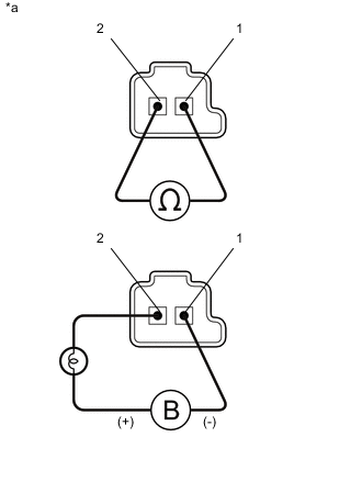
Standard Resistance Tester Connection Condition Specified Condition Terminal 1 of the shift solenoid valve SLT - Terminal 2 20°C (68°F) 5.0 to 5.6 Ω -
Apply 12 V battery voltage to the shift solenoid valve and check that the valve moves and makes an operating noise.
OK Measurement Condition Specified Condition
-
Battery positive (+) with a 21 W bulb → Terminal 2
-
Battery negative (-) → Terminal 1
Valve moves and makes an operating noise -
NG
REPLACE SHIFT SOLENOID VALVE SLT Click here
OK
-
-
INSPECT TRANSMISSION VALVE BODY ASSEMBLY
-
Check the transmission valve body assembly Click here.
OK There is no foreign matter on each valve and they operate smoothly.
OK
REPAIR OR REPLACE AUTOMATIC TRANSMISSION ASSEMBLY Click here
NG
REPAIR OR REPLACE TRANSMISSION VALVE BODY ASSEMBLY Click here
-