СИСТЕМА АВТОМАТИЧЕСКОЙ ТРАНСМИССИИ, Diagnostic DTC:P0500
| DTC Code | DTC Name |
|---|---|
| P0500 | Vehicle Speed Sensor |
DESCRIPTION
The speed sensor detects the wheel speed and sends the appropriate signals to the skid control ECU. The skid control ECU converts these wheel speed signals into a pulse signal and outputs it to the TCM via the combination meter. The TCM determines the vehicle speed based on the frequency of this pulse signal.
| DTC Code | DTC Detection Condition
|
Trouble Area |
|---|---|---|
| P0500 |
|
|
MONITOR DESCRIPTION
The TCM assumes that the vehicle is being driven when the indicated vehicle speed is more than 9 km/h (5.59 mph). If there is no speed signal from the combination meter despite this condition being met, the TCM interprets this as a malfunction in the speed signal circuit. The TCM then illuminates the MIL and stores the DTC.
WIRING DIAGRAM
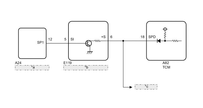
| *a | Skid Control ECU (Master Cylinder Solenoid) |
| *b | Combination Meter Assembly |
| *c | to Other ECUs |
CAUTION / NOTICE / HINT
Note
Perform registration and/or initialization when parts related to the automatic transmission are replaced Click here.
Tech Tips
After the repair, clear the DTCs and perform the following procedure to check that DTCs are not output.
-
Turn the engine switch on (IG) and wait for 3 seconds or more.*1
-
Drive the vehicle at 9 km/h (5.59 mph) or more for 5 seconds or more.*2
-
Turn the engine switch off.
-
Perform steps (*1) through (*2) again.
-
Check for DTCs again Click here.
PROCEDURE
-
CHECK OPERATION OF SPEEDOMETER
-
Drive the vehicle and check whether the operation of the speedometer in the combination meter is normal.
Tech Tips
-
The vehicle speed sensor is operating normally if the speedometer reading is normal.
-
If the speedometer does not operate, check it by following the procedure described in Speedometer Malfunction Click here.
-
NG 
GO TO MALFUNCTION IN SPEEDOMETER Click here
OK 
-
-
READ VALUE USING GTS (VEHICLE SPEED)
-
Connect the GTS to the DLC3.
-
Turn the engine switch on (IG).
-
Turn the GTS on.
-
Enter the following menus: Powertrain / ECT / Data List / Vehicle Speed.
-
Drive the vehicle.
-
In accordance with the display on the GTS, read the Data List.
ECT Tester Display Measurement Item/Range Normal Condition Diagnostic Note Vehicle Speed Vehicle speed/
Min.: 0 km/h (0 mph)
Max.: 255 km/h (158 mph)
Actual vehicle speed - OK Vehicle speed displayed on GTS and speedometer display are equal.
OK
CHECK FOR INTERMITTENT PROBLEMS Click here
NG
-
-
CHECK HARNESS AND CONNECTOR (COMBINATION METER ASSEMBLY - TCM)
-
Disconnect the E119 combination meter assembly connector.
-
Disconnect the A82 TCM connector.
-
Measure the resistance according to the value(s) in the table below.
Standard Resistance Tester Connection Condition Specified Condition E119-6 (+S) - A82-18 (SPD) Always Below 1 Ω E119-6 (+S) or A82-18 (SPD) - Body ground Always 10 kΩ or higher Tech Tips
If the wire harness has a short, check the speed signal circuit in other systems related to the vehicle speed signal (e.g. SFI system, audio system, etc.).
NG
REPAIR OR REPLACE HARNESS OR CONNECTOR (OTHER SYSTEMS RELATED TO SPEED SIGNAL)
OK
-
-
CHECK COMBINATION METER ASSEMBLY (+S VOLTAGE)
-
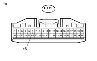
Text in Illustration *a Front view of wire harness connector
(to Combination Meter Assembly)
Disconnect the combination meter connector.
-
Turn the engine switch on (IG).
-
Measure the voltage according to the value(s) in the table below.
Standard Voltage Tester Connection Switch Condition Specified Condition E119-6 (+S) - Body ground Engine switch on (IG) 4.5 to 5.5 V
NG
REPLACE TCM Click here
OK
-
-
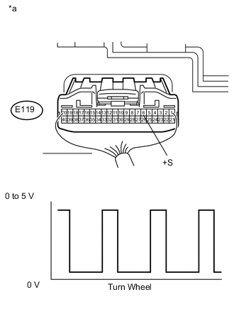
INSPECT COMBINATION METER ASSEMBLY (SPD SIGNAL OUTPUT WAVEFORM)
-
Remove the combination meter.
-
Connect the combination meter connector.
-
Move the shift lever to the neutral position.
-
Jack up the vehicle.
-
Turn the engine switch on (IG).
-
Measure the voltage according to the value(s) in the table below.
Standard Voltage Tester Connection Switch Condition Specified Condition E119-6 (+S) - Body ground Engine switch on (IG)
(Turn wheel slowly)
Voltage generated intermittently Text in Illustration *a Component with harness connected
(Combination Meter Assembly)
Tech Tips
The output voltage should fluctuate up and down, similarly to the diagram, when the wheel is turned slowly.
OK
REPLACE TCM Click here
NG
-
-
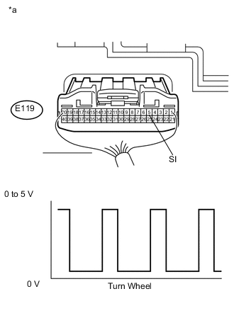
CHECK COMBINATION METER ASSEMBLY (SPD SIGNAL INPUT WAVEFORM)
-
Remove the combination meter.
-
Connect the combination meter connector.
-
Move the shift lever to the neutral position.
-
Jack up the vehicle.
-
Turn the engine switch on (IG).
-
Check the voltage between the body ground while the wheel is turned slowly.
Standard Voltage Tester Connection Switch Condition Specified Condition E119-5 (SI) - Body ground Engine switch on (IG)
(Turn wheel slowly)
Voltage generated intermittently Text in Illustration *a Component with harness connected
(Combination Meter Assembly)
Tech Tips
The output voltage should fluctuate up and down, similarly to the diagram, when the wheel is turned slowly.
OK
REPLACE COMBINATION METER ASSEMBLY Click here
NG
-
-
CHECK HARNESS AND CONNECTOR (COMBINATION METER ASSEMBLY - SKID CONTROL ECU)
-
Disconnect the E119 combination meter connector.
-
Disconnect the A24 skid control ECU connector.
-
Measure the resistance according to the value(s) in the table below.
Standard Resistance Tester Connection Condition Specified Condition E119-5 (SI) - A24-12 (SP1) Always Below 1 Ω E119-5 (SI) or A24-12 (SP1) - Body ground Always 10 kΩ or higher
OK
REPLACE SKID CONTROL ECU (MASTER CYLINDER SOLENOID) Click here
NG
REPAIR OR REPLACE HARNESS OR CONNECTOR
-