МАСЛЯНЫЙ НАСОС СНЯТИЕ

PROCEDURE
-
DISCHARGE FUEL SYSTEM PRESSURE
-
PRECAUTION
Note
After turning the engine switch off, waiting time may be required before disconnecting the cable from the battery terminal. Therefore, make sure to read the disconnecting the cable from the battery terminal notice before proceeding with work Click here.
-
DISCONNECT CABLE FROM NEGATIVE BATTERY TERMINAL
Note
When disconnecting the cable, some systems need to be initialized after the cable is reconnected Click here.
-
REMOVE FRONT BUMPER COVER
-
for Standard Click here
-
w/ Winch Click here
-
-
REMOVE TRANSMISSION OIL COOLER AIR DUCT
-
REMOVE RADIATOR SIDE DEFLECTOR LH
-
REMOVE COWL TOP VENTILATOR LOUVER SUB-ASSEMBLY
-
REMOVE FRONT FENDER APRON SEAL LH
-
REMOVE FRONT FENDER APRON SEAL FRONT RH
-
REMOVE NO. 1 ENGINE UNDER COVER SUB-ASSEMBLY
-
REMOVE NO. 2 ENGINE UNDER COVER
-
DRAIN ENGINE OIL
-
DRAIN ENGINE COOLANT
-
REMOVE V-BANK COVER SUB-ASSEMBLY
-
REMOVE AIR CLEANER HOSE ASSEMBLY
-
REMOVE AIR CLEANER ASSEMBLY
-
REMOVE RADIATOR ASSEMBLY
-
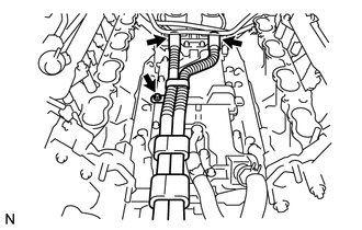
DISCONNECT ENGINE WIRE
-
Engine Room LH Side:
-
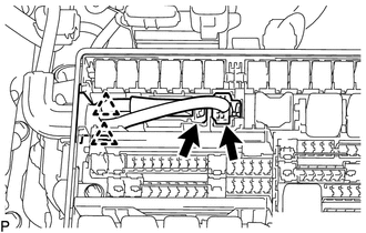
Remove the engine room relay block cover.
-
Disconnect the 2 connectors and 2 clips from the engine room junction block.
-
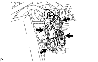
w/ Secondary Air Injection System:
Disconnect the 4 air injection control driver connectors and wire harness clamp.
-
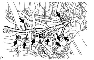
Disconnect the injector connector.
-
Disconnect the 4 ignition coil connectors.
-
Disconnect the 2 VVT sensor connectors.
-
Disconnect the 4 clamps.
-
Remove the bolt and disconnect the ground wire.
-
Disconnect the noise filter connector.
-
Disconnect the engine coolant temperature sensor connector.
-
Disconnect the 2 camshaft timing oil control valve connectors.
-
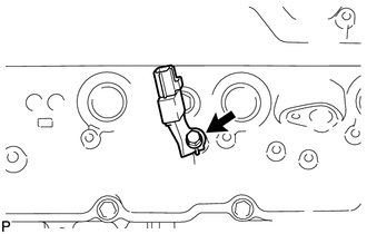
Disconnect the camshaft position sensor connector.
-
Disconnect the 3 clamps.
-
Disconnect the cooler compressor connector.
-
-
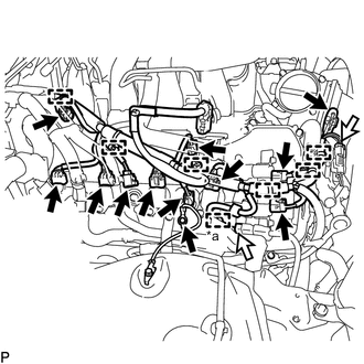
Text in Illustration *a Clamp 
Connector Engine Room RH Side:
-
Disconnect the 2 camshaft timing oil control valve connectors.
-
Disconnect the 4 ignition coil connectors.
-
Disconnect the injector connector.
-
Disconnect the 2 VVT sensor connectors.
-
Disconnect the noise filter connector.
-
Remove the bolt and disconnect the ground wire.
-
w/ Secondary Air Injection System:
Disconnect the 2 air pump connectors and clamp.
-
Disconnect the throttle position sensor and throttle control motor connector.
-
Disconnect the 6 clamps.
-
-
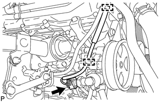
Disconnect the 2 clamps and power steering oil pressure switch connector.
-
-
DISCONNECT AIR PUMP HOSE AND WIRE HARNESS (w/ Secondary Air Injection System)
-

Text in Illustration *1 No. 2 Air Hose *2 No. 3 Air Hose Disconnect the No. 2 and No. 3 air hoses.
-
Disconnect the 2 clamps.
-
-
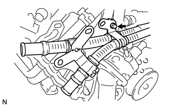
DISCONNECT WATER PIPE AND HOSE SUB-ASSEMBLY
-
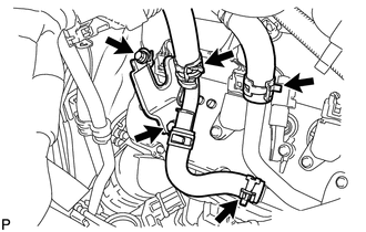
Disconnect the 3 hoses.
-
Remove the 2 bolts and disconnect the water pipe and hose from the cylinder head cover.
-
-
DISCONNECT COOLER COMPRESSOR ASSEMBLY
-
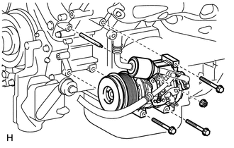
Remove the 3 bolts, nut and stud bolt, and disconnect the cooler compressor.
Tech Tips
It is not necessary to completely remove the compressor. With the hoses connected to the compressor, hang the compressor on the vehicle body with a rope.
-
-
DISCONNECT NO. 2 FUEL TUBE SUB-ASSEMBLY
-
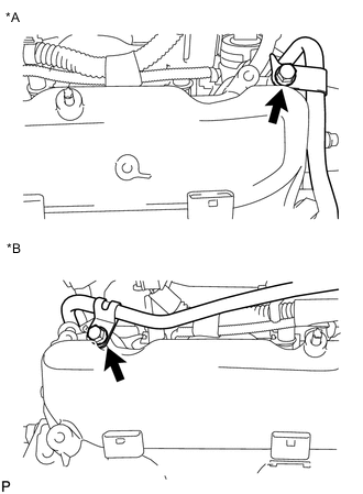
Text in Illustration *A LH Side *B RH Side Remove the 2 bolts and disconnect the fuel tube.
-
-
REMOVE OIL FILTER ELEMENT
-
REMOVE ENGINE OIL LEVEL DIPSTICK GUIDE
-
REMOVE OIL PRESSURE SENDER GAUGE ASSEMBLY
-
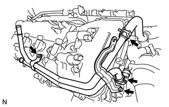
REMOVE NO. 2 WATER BY-PASS PIPE SUB-ASSEMBLY
-
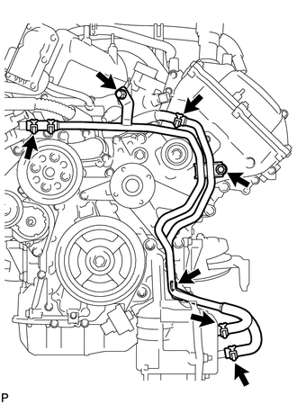
Remove the 3 bolts.
-
Disconnect the 4 hoses and remove the water by-pass pipe.
-
-
REMOVE NO. 1 OIL COOLER BRACKET
-
REMOVE OIL FILTER BRACKET
-
REMOVE INTAKE MANIFOLD
-
DISCONNECT VANE PUMP ASSEMBLY
-
Remove the 2 bolts and disconnect the vane pump.
-
-
DISCONNECT OIL COOLER PIPE ASSEMBLY
-
REMOVE GENERATOR ASSEMBLY
-
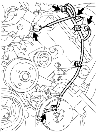
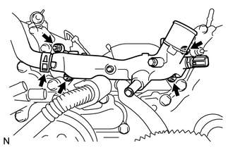
REMOVE NO. 1 WATER BY-PASS HOSE
-
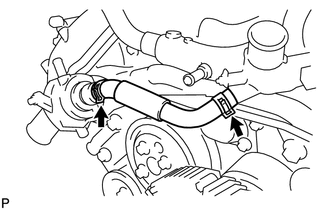
Remove the No. 1 water by-pass hose by disconnecting the hose from the water inlet housing and front water by-pass joint.
-
-
REMOVE WATER BY-PASS PIPE SUB-ASSEMBLY
-
w/ Secondary Air Injection System:
Remove the bolt and disconnect the air tube.
-
Disconnect the 2 hoses.
-
Remove the 2 bolts and water by-pass pipe.
-
-
REMOVE FRONT WATER BY-PASS JOINT
-
Disconnect the No. 2 water by-pass hose from the water by-pass joint.
-
Remove the 4 nuts, water by-pass joint and 2 gaskets.
-
-
REMOVE NO. 2 ENGINE COVER
-
REMOVE NO. 1 ENGINE COVER
-
REMOVE AIR PIPE SUB-ASSEMBLY (w/ Secondary Air Injection System)
-
Remove the bolt, disconnect the 2 hoses, and remove the air pipe.
-
-
REMOVE WATER INLET HOUSING
-
Remove the 3 bolts, water inlet housing and gasket.
-
-
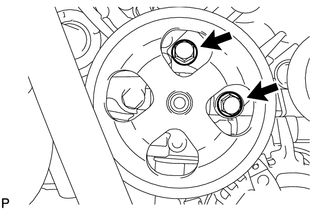
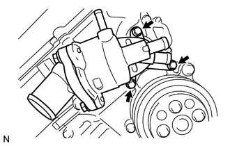
REMOVE WATER PUMP PULLEY
-
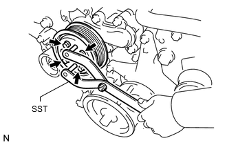
Using SST, hold the water pump pulley.
- SST
- 09960-10010 ( 09962-01000, 09963-01000 )
-
Remove the 4 bolts and water pump pulley.
-
-
REMOVE NO. 1 IDLER PULLEY SUB-ASSEMBLY
-
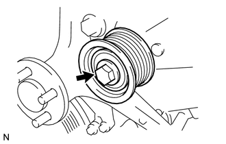
Remove the bolt and idler pulley.
-
-
REMOVE FLUID COUPLING BRACKET
-
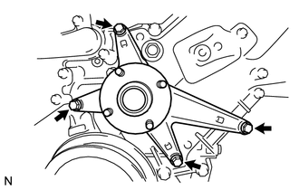
Remove the 4 bolts and fluid coupling bracket.
-
-
REMOVE V-RIBBED BELT TENSIONER ASSEMBLY
-
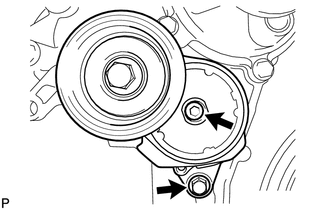
Remove the standard bolt, 6 mm hexagon wrench bolt and belt tensioner.
-
-
REMOVE IGNITION COIL ASSEMBLY
-
Remove the 8 bolts and 8 ignition coils.
-
-
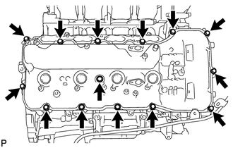
REMOVE CYLINDER HEAD COVER SUB-ASSEMBLY LH
-
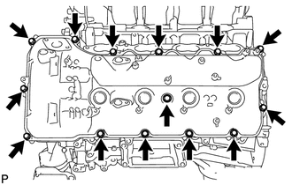
Remove the 14 bolts, seal washer, cylinder head cover and gasket.
Tech Tips
Make sure the removed parts are returned to the same places they were removed from.
-
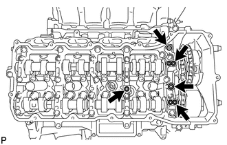
Remove the 5 gaskets from the camshaft bearing caps (No. 2, No. 3).
-
-
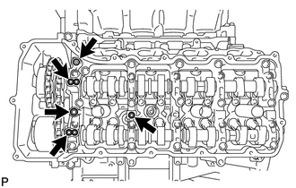
REMOVE CYLINDER HEAD COVER SUB-ASSEMBLY RH
-
Remove the bolt and noise filter.
-
Remove the 14 bolts, seal washer, cylinder head cover and gasket.
Tech Tips
Make sure the removed parts are returned to the same places they were removed from.
-
Remove the 5 gaskets from the camshaft bearing caps (No. 1, No. 3).
-
-
REMOVE SPARK PLUG TUBE GASKET
-
REMOVE CRANKSHAFT PULLEY
-
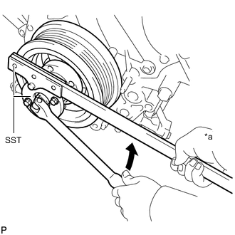
Text in Illustration *a Hold 
Turn Using SST, loosen the crankshaft pulley set bolt until 2 or 3 threads are engaged.
- SST
- 09213-70011
- 09330-00021
-
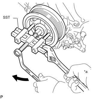
Text in Illustration *a Hold Turn Using the pulley set bolt and SST, remove the crankshaft pulley.
- SST
- 09950-50013 ( 09951-05010, 09952-05010, 09953-05010, 09954-05011 )
-
-
DISCONNECT WIRE HARNESS CLAMP BRACKET
-
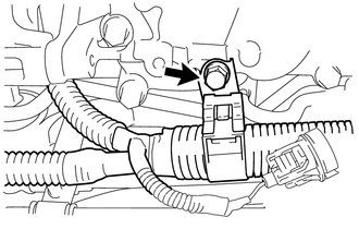
Remove the bolt and disconnect the bracket.
-
-
REMOVE CRANKSHAFT TIMING GEAR KEY
-
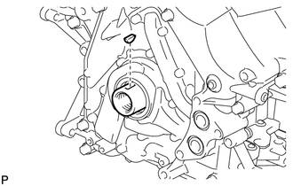
Using a screwdriver, remove the timing gear key from the crankshaft.
-
-
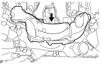
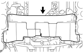
REMOVE TIMING CHAIN COVER SUB-ASSEMBLY
-
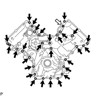
Remove the 28 bolts and nut shown in the illustration.
Text in Illustration Bolt Nut -
Remove the timing chain cover by prying between the timing chain cover and cylinder head or cylinder block with a screwdriver as shown in the illustration.
Note
Be careful not to damage the contact surfaces of the cylinder head, cylinder block and chain cover.
Tech Tips
Tape the screwdriver tip before use.
-
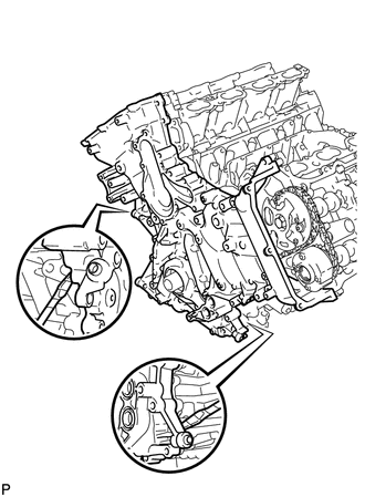
Remove the oil pump gasket from the cylinder block.
-
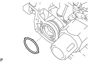
Remove the O-ring from the oil pan.
-
-
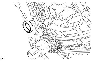
REMOVE WATER INLET PIPE
-
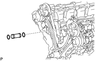
Remove the water inlet pipe.
-
Remove the 2 O-rings from the water inlet pipe.
-