ВОЗДУШНЫЙ НАГНЕТАТЕЛЬ (для моделей с вспомогательной системой подачи воздуха в нейтрализатор) СНЯТИЕ
PROCEDURE
-
PRECAUTION
Note
After turning the engine switch off, waiting time may be required before disconnecting the cable from the battery terminal. Therefore, make sure to read the disconnecting the cable from the battery terminal notice before proceeding with work Click here.
-
DISCONNECT CABLE FROM NEGATIVE BATTERY TERMINAL
Note
When disconnecting the cable, some systems need to be initialized after the cable is reconnected Click here.
-
REMOVE FRONT FENDER SPLASH SHIELD SUB-ASSEMBLY RH
-
REMOVE FRONT FENDER LINER RH
-
Remove the screw, and disconnect the front fender liner RH from the front bumper cover.
-
Using a T30 "TORX" socket, remove the 3 screws.
-
Remove the 5 clips.
-
Partially remove the front fender liner RH.
Tech Tips
It is not necessary to fully remove the front fender liner RH. Partially remove it so that the air pump assembly can be removed.
-
-
REMOVE FRONT FENDER APRON SEAL FRONT RH
-
REMOVE V-BANK COVER SUB-ASSEMBLY
-
REMOVE AIR CLEANER HOSE ASSEMBLY
-
REMOVE AIR CLEANER ASSEMBLY
-
REMOVE NO. 2 AIR INJECTION SYSTEM HOSE
-
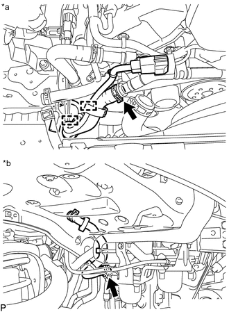
Text in Illustration *a Engine Room Side *b Front Fender RH Inside Engine Room Side:
-
Detach the 2 clamps.
-
Slide the clamp indicated by the arrow in the illustration and disconnect the No. 2 air injection system hose from the air tube sub-assembly.
-
-
Front Fender RH Inside:
-
Slide the clamp and disconnect the No. 2 air injection system hose from the air pump assembly.
-
-
-
REMOVE NO. 3 AIR INJECTION SYSTEM HOSE
-
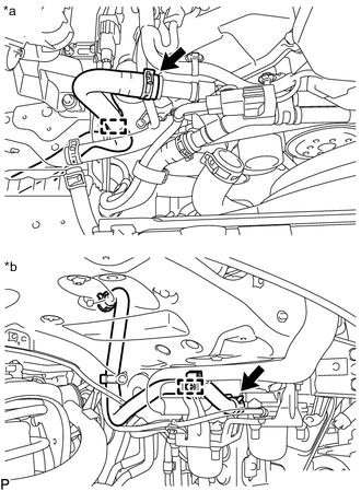
Text in Illustration *a Engine Room Side *b Front Fender RH Inside Engine Room Side:
-
Detach the clamp.
-
Slide the clamp indicated by the arrow in the illustration and disconnect the No. 3 air injection system hose from the air tube sub-assembly.
-
-
Front Fender RH Inside:
-
Detach the clamp.
-
Slide the clamp indicated by the arrow in the illustration and disconnect the No. 3 air injection system hose from the air pump assembly.
-
-
-
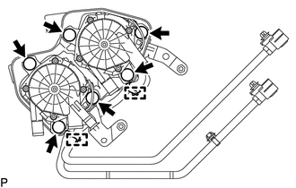
REMOVE AIR PUMP ASSEMBLY WITH BRACKET
-
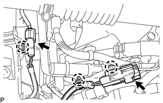
Disconnect the 2 air pump assembly connectors to detach the 3 wire harness clamps.
-
Remove the 2 bolts, 2 nuts and air pump assembly with bracket.
-
-
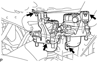
REMOVE AIR PUMP INLET
-
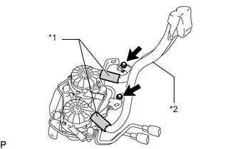
Text in Illustration *1 No. 1 Air Injection System Hose *2 Air Pump Inlet Remove the 2 bolts.
-
Disconnect the air pump inlet from the 2 No. 1 air injection system hoses to remove it.
-
-
REMOVE NO. 1 AIR INJECTION SYSTEM HOSE
-
Remove the 2 No. 1 air injection system hoses.
-
-
REMOVE AIR PUMP ASSEMBLY
-
Using a clip remover, detach the 2 wire harness clamps and remove the 2 air pump assemblies from the air pump bracket.
-
Disconnect the 6 air pump insulators.
-