БЛОК ДВИГАТЕЛЯ СНЯТИЕ

PROCEDURE
-
REMOVE ENGINE WIRE
-
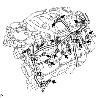
Engine LH Side:
-
Disconnect the 2 camshaft timing control valve connectors.
-
Disconnect the 4 ignition coil connectors.
-
Disconnect the 2 VVT sensor connectors.
-
Disconnect the camshaft position sensor connector.
-
Disconnect the vacuum switching valve connector (for ACIS).
-
Disconnect the purge VSV connector.
-
Disconnect the engine coolant temperature sensor connector.
-
Disconnect the fuel injector connector.
-
Disconnect the noise filter connector.
-
Remove the bolt and disconnect the 7 clamps.
-
-
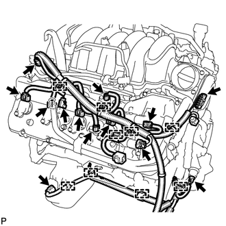
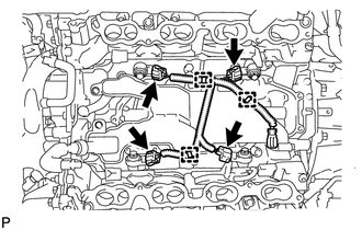
Engine RH Side:
-
Disconnect the 2 camshaft timing control valve connectors.
-
Disconnect the 4 ignition coil connectors.
-
Disconnect the 2 VVT sensor connectors.
-
Disconnect the fuel injector connector.
-
Disconnect the noise filter connector.
-
Disconnect the throttle sensor connector.
-
Disconnect the oil pressure sender gauge connector.
-
Disconnect the oil level sensor connector.
-
Disconnect the 9 clamps.
-
-
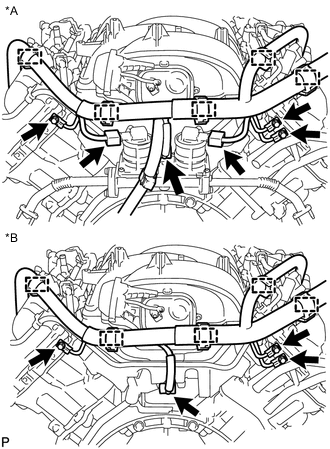
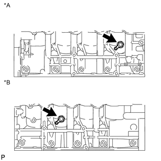
Text in Illustration *A w/ Secondary Air Injection System *B w/o Secondary Air Injection System Engine Rear Side:
-
w/ Secondary Air Injection System:
Disconnect the 2 air switching valve connectors.
-
Disconnect the sensor wire connector.
-
Disconnect the 5 clamps.
-
Remove the 3 bolts.
-
-
Remove the engine wire.
-
-
REMOVE NO. 1 ENGINE COVER SUB-ASSEMBLY
-
REMOVE NO. 3 ENGINE COVER
-
REMOVE NO. 1 FUEL HOSE
-
Remove the fuel hose Click here.
-
-
DISCONNECT NO. 2 FUEL TUBE
-
DISCONNECT NO. 1 FUEL TUBE
-
REMOVE FUEL DELIVERY PIPE SUB-ASSEMBLY LH
-
REMOVE FUEL DELIVERY PIPE SUB-ASSEMBLY RH
-
REMOVE FUEL INJECTOR ASSEMBLY
-
REMOVE INTAKE MANIFOLD
-
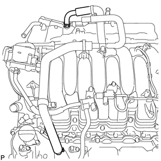
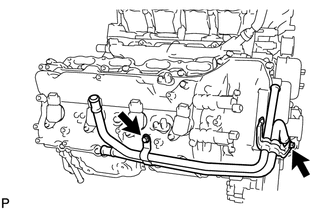
Disconnect the ventilation hose from the ventilation pipe of the cylinder head cover LH and RH.
-
Disconnect the 2 water by-pass hoses.
-
Disconnect the No. 1 ventilation hose.
-
Remove the bolt and wire bracket from the intake manifold.
-
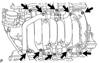
Remove the 2 nuts, 8 bolts, intake manifold and 2 gaskets.
-
-
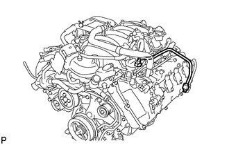
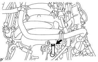
REMOVE NO. 2 FUEL TUBE
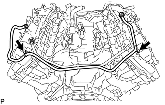
-
Remove the 2 bolts and No. 2 fuel tube.
-
-
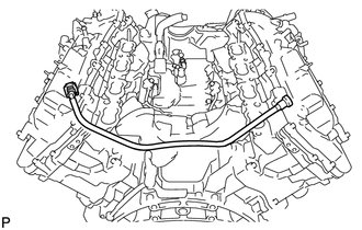
REMOVE NO. 1 FUEL TUBE
-
REMOVE NO. 2 ENGINE COVER
-
REMOVE NO. 1 ENGINE COVER
-
REMOVE NO. 2 WATER BY-PASS PIPE SUB-ASSEMBLY
-
REMOVE NO. 1 WATER BY-PASS HOSE
-
REMOVE FRONT WATER BY-PASS JOINT
-
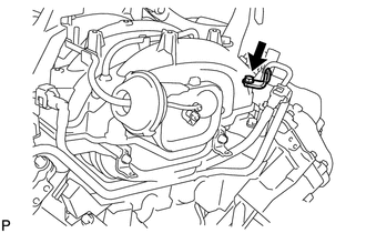
REMOVE AIR PIPE SUB-ASSEMBLY (w/ Secondary Air Injection System)
-
Remove the 2 bolts, air pipe and 2 No. 1 air hoses.
-
-
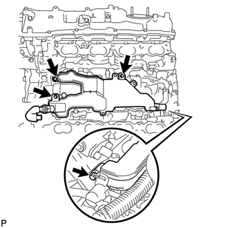
REMOVE WATER INLET HOUSING
-
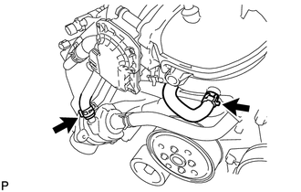
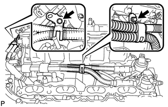
REMOVE WATER BY-PASS PIPE SUB-ASSEMBLY
-
Remove the 2 bolts and water by-pass pipe.
-
-
REMOVE AIR SWITCHING VALVE ASSEMBLY (w/ Secondary Air Injection System)
-
REMOVE NO. 2 AIR TUBE (w/ Secondary Air Injection System)
-
REMOVE NO. 3 AIR TUBE (w/ Secondary Air Injection System)
-
REMOVE SENSOR WIRE
-
Disconnect the 4 knock sensor connectors.
-
Disconnect the 3 clamps. Then remove the sensor wire.
-
-
REMOVE SEPARATOR CASE
-
Remove the 4 bolts and separator case.
-
-
REMOVE KNOCK SENSOR
-
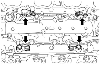
Remove the 4 bolts and 4 knock sensors.
-
-
REMOVE CYLINDER BLOCK WATER DRAIN COCK SUB-ASSEMBLY
Text in Illustration *A RH *B LH
-
Remove the 2 water drain cock plugs from the water drain cocks.
-
Remove the 2 water drain cocks from the cylinder block.
-
-
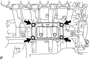
REMOVE FRONT NO. 1 ENGINE MOUNTING BRACKET RH
-
Remove the 4 bolts and mounting bracket.
-
-
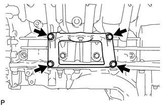
REMOVE FRONT NO. 1 ENGINE MOUNTING BRACKET LH
-
Remove the 4 bolts and mounting bracket.
-
-
REMOVE IGNITION COIL ASSEMBLY
-
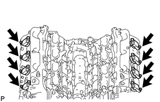
Remove the 8 bolts and 8 ignition coils.
-
-
REMOVE NOISE FILTER
-
Remove the 2 bolts and 2 noise filters from the cylinder head cover.
-