ПРОКЛАДКА ГОЛОВКИ БЛОКА ЦИЛИНДРОВ УСТАНОВКА
PROCEDURE
-
INSPECT CYLINDER HEAD SET BOLT
-
INSPECT CYLINDER HEAD SUB-ASSEMBLY
-
INSTALL CYLINDER HEAD SUB-ASSEMBLY RH
-
Clean the cylinder block with solvent.
-
Set the piston of the No. 1 cylinder to slightly ATDC.
-
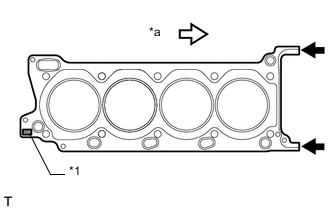
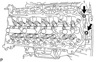
Text in Illustration *1 Lot No. *a Front Place the cylinder head gasket on the cylinder block surface with the front face of the Lot No. stamp upward.
Note
-
Be careful of the installation direction.
-
Make sure that no oil is on the front end (indicated by the arrows) of the cylinder head gasket.
-
-
Place the cylinder head on the cylinder block.
Note
-
Ensure that no oil is on the mounting surface of the cylinder head.
-
Gently place the cylinder head in order not to damage the gasket with the bottom part of the head.
Tech Tips
The cylinder head bolts are tightened in 3 progressive steps.
-
-
Apply a light coat of engine oil to the threads and under the heads of the cylinder head bolts.
-

Step 1:
-
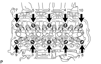
Using a 10 mm bi-hexagon wrench, install and uniformly tighten the 10 cylinder head bolts with the plate washers in several steps in the sequence shown in the illustration.
- Torque:
- 36 N*m { 367 kgf*cm, 27 ft.*lbf }
-
-
Step 2:
-
Mark the front side of each cylinder head bolt head with paint.
-
Tighten the cylinder head bolts another 90°.
-
-
Step 3:
-
Tighten the cylinder head bolts an additional 90°.
-
Check that the paint marks are now at a 180° angle to the front.
-
-
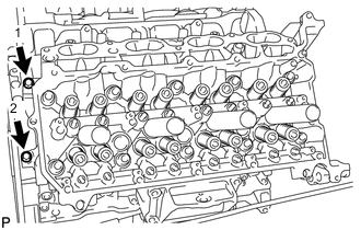
Install and uniformly tighten the 2 bolts in the sequence shown in the illustration.
- Torque:
- 21 N*m { 214 kgf*cm, 15 ft.*lbf }
-
-
INSTALL CYLINDER HEAD SUB-ASSEMBLY LH
-
Clean the cylinder block with solvent.
-
Set the piston of the No. 1 cylinder to slightly ATDC.
-
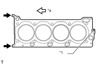
Text in Illustration *1 Lot No. *a Front Place the cylinder head gasket on the cylinder block surface with the front face of the Lot No. stamp upward.
Note
-
Be careful of the installation direction.
-
Make sure that no oil is on the front end (indicated by the arrows) of the cylinder head gasket.
-
-
Place the cylinder head on the cylinder block.
Note
-
Ensure that no oil is on the mounting surface of the cylinder head.
-
Gently place the cylinder head in order not to damage the gasket with the bottom part of the head.
Tech Tips
The cylinder head bolts are tightened in 3 progressive steps.
-
-
Apply a light coat of engine oil to the threads and under the heads of the cylinder head bolts.
-
Step 1:
Tech Tips
The cylinder head bolts are tightened in 3 progressive steps.
-
Using a 10 mm bi-hexagon wrench, install and uniformly tighten the 10 cylinder head bolts with the plate washers in several steps in the sequence shown in the illustration.
- Torque:
- 36 N*m { 367 kgf*cm, 27 ft.*lbf }
-
-
Step 2:
-
Mark the front side of each cylinder head bolt head with paint.
-
Tighten the cylinder head bolts another 90°.
-
-
Step 3:
-
Tighten the cylinder head bolts an additional 90°.
-
Check that the paint marks are now at a 180° angle to the front.
-
-
Install and uniformly tighten the 2 bolts in the sequence shown in the illustration.
- Torque:
- 21 N*m { 214 kgf*cm, 15 ft.*lbf }
-
-
INSTALL VALVE STEM CAP
-
INSTALL VALVE LASH ADJUSTER ASSEMBLY
-
INSTALL NO. 1 VALVE ROCKER ARM SUB-ASSEMBLY
-
INSTALL CAMSHAFT
-
INSTALL EXHAUST MANIFOLD SUB-ASSEMBLY