СИСТЕМА SFI (для моделей с вспомогательной системой подачи воздуха в нейтрализатор) ECM Power Source Circuit
DESCRIPTION
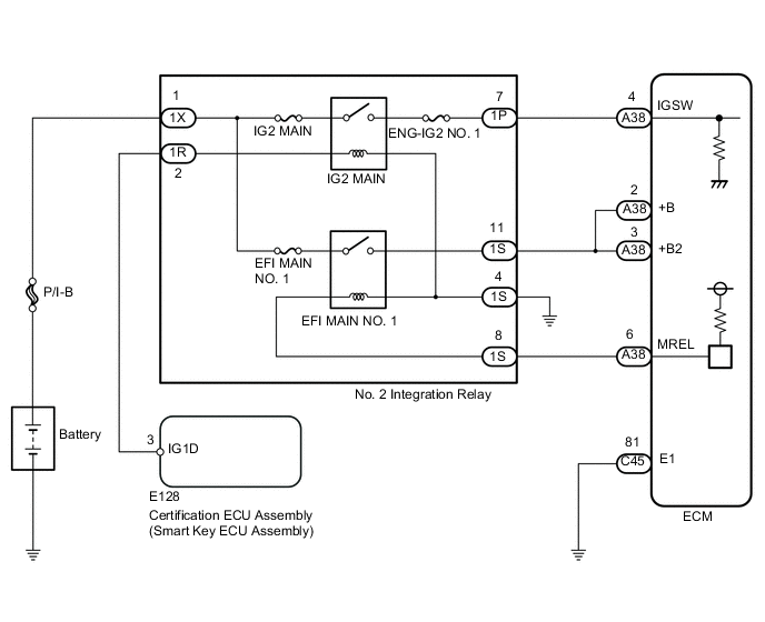
When the engine switch is turned on (IG), the battery voltage is applied to the IGSW of the ECM. The output signal from the MREL terminal of the ECM causes a current to flow to the coil, closing the contacts of the No. 2 integration relay (EFI MAIN NO. 1 relay) and supplying power to either terminal +B or +B2 of the ECM.
WIRING DIAGRAM
CAUTION / NOTICE / HINT
Note
Inspect the fuses for circuits related to this system before performing the following inspection procedure.
PROCEDURE
-
INSPECT NO. 2 INTEGRATION RELAY (POWER SOURCE)
-
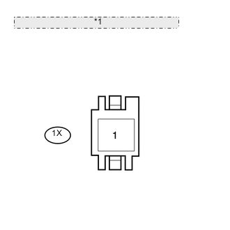
*1 Front view of wire harness connector: (to No. 2 integration relay) Disconnect the No. 2 integration relay connector.
-
Measure the voltage according to the value(s) in the table below.
Standard Voltage Tester Connection Switch Condition Specified Condition 1X-1 - Body ground Always 11 to 14 V
NG 
REPAIR OR REPLACE HARNESS OR CONNECTOR (BATTERY - NO. 2 INTEGRATION RELAY)
OK 
-
-
CHECK HARNESS AND CONNECTOR (NO. 2 INTEGRATION RELAY - BODY GROUND)
-
Disconnect the No. 2 integration relay connector.
-
Measure the resistance according to the value(s) in the table below.
Standard Resistance Tester Connection Condition Specified Condition 1S-4 - Body ground Always Below 1 Ω
NG
REPAIR OR REPLACE HARNESS OR CONNECTOR
OK
-
-
INSPECT NO. 2 INTEGRATION RELAY (IG2 MAIN, EFI MAIN NO. 1)
-
Inspect the No. 2 integration relay Click here.
NG
REPLACE NO. 2 INTEGRATION RELAY
OK
-
-
CHECK HARNESS AND CONNECTOR (NO. 2 INTEGRATION RELAY - ECM)
-
Disconnect the ECM connector.
-
Disconnect the No. 2 integration relay connector.
-
Measure the resistance according to the value(s) in the table below.
Standard Resistance Tester Connection Condition Specified Condition A38-6 (MREL) - 1S-8 Always Below 1 Ω A38-2 (+B) - 1S-11 Always Below 1 Ω A38-3 (+B2) - 1S-11 Always Below 1 Ω A38-6 (MREL) or 1S-8 - Body ground Always 10 kΩ or higher A38-2 (+B) or 1S-11 - Body ground Always 10 kΩ or higher A38-3 (+B2) or 1S-11 - Body ground Always 10 kΩ or higher
NG
REPAIR OR REPLACE HARNESS OR CONNECTOR
OK
-
-
CHECK HARNESS AND CONNECTOR (ECM - BODY GROUND)
-
Disconnect the ECM connector.
-
Measure the resistance according to the value(s) in the table below.
Standard Resistance Tester Connection Condition Specified Condition C45-81 (E1) - Body ground Always Below 1 Ω
NG
REPAIR OR REPLACE HARNESS OR CONNECTOR
OK
-
-
INSPECT ECM (IGSW VOLTAGE)
-
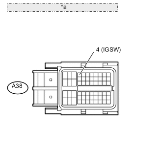
*a Front view of wire harness connector: (to ECM) Disconnect the ECM connectors.
-
Turn the engine switch on (IG).
-
Measure the voltage according to the value(s) in the table below.
Standard Voltage Tester Connection Switch Condition Specified Condition A38-4 (IGSW) - Body ground Engine switch on (IG) 11 to 14 V
OK
REPLACE ECM Click here
NG
-
-
CHECK HARNESS AND CONNECTOR (NO. 2 INTEGRATION RELAY - ECM)
-
Disconnect the ECM connector.
-
Disconnect the No. 2 integration relay connector.
-
Measure the resistance according to the value(s) in the table below.
Standard Resistance Tester Connection Condition Specified Condition A38-4 (IGSW) - 1P-7 Always Below 1 Ω A38-4 (IGSW) or 1P-7 - Body ground Always 10 kΩ or higher
NG
REPAIR OR REPLACE HARNESS OR CONNECTOR
OK
-
-
CHECK HARNESS AND CONNECTOR (SMART KEY ECU ASSEMBLY - NO. 2 INTEGRATION RELAY)
-
Disconnect the smart key ECU assembly connector.
-
Disconnect the No. 2 integration relay connector.
-
Measure the resistance according to the value(s) in the table below.
Standard Resistance Tester Connection Condition Specified Condition E128-3 (IGSW) - 1R-2 Always Below 1 Ω E128-3 (IGSW) or 1R-2 - Body ground Always 10 kΩ or higher
OK
CHECK ENTRY AND START SYSTEM Click here
NG
REPAIR OR REPLACE HARNESS OR CONNECTOR
-