СИСТЕМА SFI (для моделей с вспомогательной системой подачи воздуха в нейтрализатор), Diagnostic DTC:P0014, P0015, P0024, P0025
| DTC Code | DTC Name |
|---|---|
| P0014 | Camshaft Position "B" - Timing Over-Advanced or System Performance (Bank 1) |
| P0015 | Camshaft Position "B" - Timing Over-Retarded (Bank 1) |
| P0024 | Camshaft Position "B" - Timing Over-Advanced or System Performance (Bank 2) |
| P0025 | Camshaft Position "B" - Timing Over-Retarded (Bank 2) |
DESCRIPTION
Tech Tips
If DTC P0014, P0015, P0024 or P0025 is output, check the VVT (Variable Valve Timing) system.
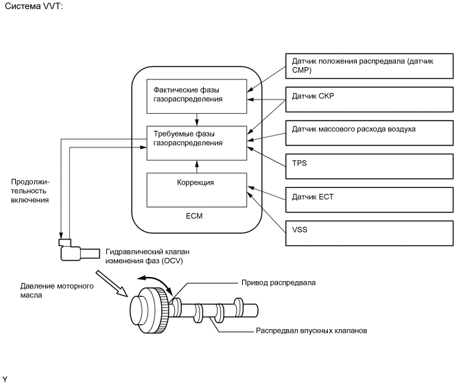
The Variable Valve Timing (VVT) system includes the ECM, OCV and VVT controller. The ECM sends a target duty-cycle control signal to the OCV. This control signal regulates the oil pressure supplied to the VVT controller. Camshaft timing control is performed according to engine operating conditions such as the intake air volume, throttle valve position and engine coolant temperature. The ECM controls the OCV based on the signals transmitted by several sensors. The VVT controller regulates the exhaust camshaft angle using oil pressure through the OCV. As a result, the relative positions of the camshaft and crankshaft are optimized, the engine torque and fuel economy improve, and the exhaust emissions decrease under overall driving conditions. The ECM detects the actual exhaust valve timing using signals from the camshaft and crankshaft position sensors, and performs feedback control. This is how the target exhaust valve timing is verified by the ECM.
| DTC Code | DTC Detection Condition | Trouble Area |
|---|---|---|
| P0014 P0024 |
The exhaust valve timing is not adjusted in the valve timing advance range (2 trip detection logic). |
|
| P0015 P0025 |
The exhaust valve timing is not adjusted in the valve timing retard range (1 trip detection logic). |
|
MONITOR DESCRIPTION
-
The ECM optimizes the exhaust valve timing using the VVT (Variable Valve Timing) system to control the exhaust camshaft. The VVT system includes the ECM, Camshaft Oil Control Valve (OCV) and VVT controller.
-
The ECM sends a target duty-cycle control signal to the OCV. This control signal regulates the oil pressure supplied to the VVT controller. The VVT controller can advance or retard the exhaust camshaft.
If the difference between the target and actual exhaust valve timing is large, and changes in actual exhaust valve timing are small, the ECM interprets this as the VVT controller stuck malfunction and stores DTC(s).
-
Example:
A DTC is stored when the following conditions 1 and 2 are met:
-
1. It takes 5 seconds or more to change the valve timing by 5°CA.
-
2. After the above condition 1 is met, the camshaft timing oil control valve is forcibly activated during 10 seconds.
-
DTCs P0014 and P0024 (Advanced Cam Timing) are subject to 2 trip detection logic.
-
DTCs P0015 and P0025 (Retarded Cam Timing) are subject to 1 trip detection logic.
These DTCs indicate that the VVT controller cannot operate properly due to OCV malfunctions or the presence of foreign objects in the OCV.
-
The monitor will not run unless the following conditions are met:
-
The engine is warm (the engine coolant temperature is 75°C [167°F] or higher).
-
The vehicle has been driven at more than 64 km/h (40 mph) for 3 minutes.
-
The engine has idled for 3 minutes.
WIRING DIAGRAM
Refer to DTC P0013 Click here.
CAUTION / NOTICE / HINT
Tech Tips
| Abnormal Bank | Advanced Timing Over (Valve Timing is Out of Specified Range) |
Retarded Timing Over (Valve Timing is Out of Specified Range) |
|---|---|---|
| Bank 1 | P0014 | P0015 |
| Bank 2 | P0024 | P0025 |
-
If DTC P0014 or P0015 is output, check the bank 1 VVT system for exhaust side circuit.
-
Bank 1 refers to the bank that includes the No. 1 cylinder*.
*: The No. 1 cylinder is the cylinder which is farthest from the transmission.
-
If DTC P0024 or P0025 is output, check the bank 2 VVT system for exhaust side circuit.
-
Bank 2 refers to the bank that does not include the No. 1 cylinder.
-
Read freeze frame data using the intelligent tester. Freeze frame data records the engine condition when malfunctions are detected. When troubleshooting, freeze frame data can help determine if the vehicle was moving or stationary, if the engine was warmed up or not, if the air-fuel ratio was lean or rich, and other data from the time the malfunction occurred.
PROCEDURE
-
CHECK ANY OTHER DTCS OUTPUT (IN ADDITION TO DTC P0014, P0015, P0024 OR P0025)
-
Connect the intelligent tester to the DLC3.
-
Turn the engine switch on (IG) and turn the tester on.
-
Enter the following menus: Powertrain / Engine and ECT / DTC.
-
Read DTCs.
Result Result Proceed to P0014, P0015, P0024 or P0025 A P0014, P0015, P0024 or P0025 and other DTCs B Tech Tips
If any DTCs other than P0014, P0015, P0024 or P0025 are output, troubleshoot those DTCs first.
B 
GO TO DTC CHART Click here
A 
-
-
PERFORM ACTIVE TEST USING INTELLIGENT TESTER (OPERATE OCV)
-
Connect the intelligent tester to the DLC3.
-
Turn the tester on.
-
Warm up the engine.
-
Turn the A/C on.
-
Enter the following menus: Powertrain / Engine and ECT / Active Test / Control the VVT Exhaust Linear (Bank 1) or Control the VVT Exhaust Linear (Bank 2).
-
Check the engine speed while operating the camshaft timing oil control valve using the tester.
OK Operation Specified Condition 0% Normal engine speed 100% Engine idles roughly or stalls Tech Tips
Refer to "Data List / Active Test" [VVT Ex OCV Duty #1, VVT Ex Chg Angle #1, VVT Ex OCV Duty #2 and VVT Ex Chg Angle #2] Click here.
NG 
CHECK VALVE TIMING (CHECK FOR LOOSE AND JUMPED TEETH ON TIMING CHAIN) Click here
OK
-
-
CHECK WHETHER DTC OUTPUT RECURS (DTC P0014, P0015, P0024 OR P0025)
-
Connect the intelligent tester to the DLC3.
-
Turn the tester on.
-
Clear the DTCs Click here.
-
Warm up the engine.
-
Switch the ECM from normal mode to check mode using the tester Click here.
-
With the engine warmed up, idle it for 1 minute. Then drive the vehicle for 5 minutes.
-
Read DTCs using the tester.
OK No DTC output.
OK
CHECK FOR INTERMITTENT PROBLEMS Click here
NG
-
-
CHECK VALVE TIMING (CHECK FOR LOOSE AND JUMPED TEETH ON TIMING CHAIN)
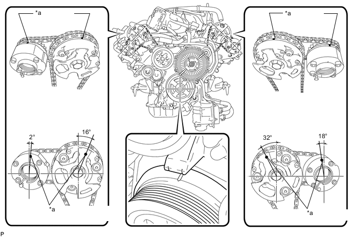
*a Timing Mark
-
Remove the cylinder head cover LH and RH.
-
Turn the crankshaft pulley, and align its groove with the timing mark "0" of the timing chain cover.
-
Check that the timing marks of the camshaft timing gears and camshaft timing exhaust gears are at the positions shown in the illustration.
OK Timing marks on camshaft timing gears are aligned as shown in the illustration.
NG
ADJUST VALVE TIMING Click here
OK
-
-
INSPECT CAMSHAFT OIL CONTROL VALVE ASSEMBLY (OCV FOR EXHAUST CAMSHAFT)
-
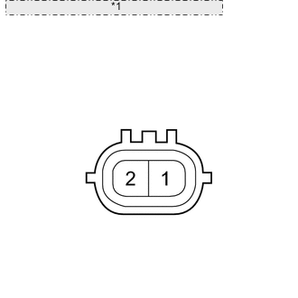
*1 Component without harness connected: (Oil Control Valve) Remove the OCV Click here.
-
Measure the resistance according to the value(s) in the table below.
Standard Resistance Tester Connection Condition Specified Condition 1 - 2 20°C (68°F) 6.9 to 7.9 Ω -
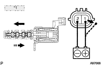
*1 Valve Moves Check the valve operation.
OK Measurement Condition Specified Condition No battery voltage applied to terminals 1 and 2 → Battery voltage applied to terminals 1 and 2 Valve moves quickly
NG
REPLACE CAMSHAFT OIL CONTROL VALVE ASSEMBLY Click here
OK
-
-
INSPECT OIL CONTROL VALVE FILTER
-
Remove the oil control valve filter Click here.
-
Check that the filter is not clogged.
OK Filter is not clogged.
NG
CLEAN OIL CONTROL VALVE FILTER
OK
-
-
REPLACE CAMSHAFT TIMING EXHAUST GEAR
-
Replace the camshaft timing exhaust gear Click here.
NEXT
-
-
CHECK WHETHER DTC OUTPUT RECURS
-
Connect the intelligent tester to the DLC3.
-
Turn the tester on.
-
Clear the DTCs Click here.
-
Warm up the engine.
-
Switch the ECM from normal mode to check mode using the tester Click here.
-
With the engine warmed up, idle it for 1 minute. Then drive the vehicle for 5 minutes.
-
Read the output DTCs using the tester.
OK No DTC output. Tech Tips
DTC P0014, P0015, P0024 or P0025 is output when foreign objects in the engine oil are caught in some parts of the system. These codes will stay stored even if the system returns to normal after a short time. These foreign objects are then captured by the oil filter, thus eliminating the source of the problem.
OK
SYSTEM IS OK
NG
REPLACE ECM Click here
-