PROCEDURE
- Click here
INSPECT HEADLIGHT RELAY (H-LP LO, H-LP LH Relay)
-
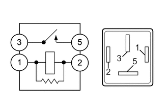
Measure the resistance according to the value(s) in the table below.
Standard Resistance Tester Connection Condition Specified Condition 3 - 5 Battery voltage is not applied to terminals 1 and 2 10 kΩ or higher Battery voltage is applied to terminals 1 and 2 Below 1 Ω If the result is not as specified, replace the headlight relay.
-
- Click here
INSPECT HEADLIGHT RELAY (H-LP HI, H-LP RH Relay)
-
Measure the resistance according to the value(s) in the table below.
Standard Resistance Tester Connection Condition Specified Condition 3 - 5 Battery voltage is not applied to terminals 1 and 2 10 kΩ or higher Battery voltage is applied to terminals 1 and 2 Below 1 Ω If the result is not as specified, replace the headlight relay.
-
- Click here
INSPECT FOG LIGHT RELAY (FR FOG)
-
Measure the resistance according to the value(s) in the table below.
Standard Resistance Tester Connection Condition Specified Condition 3 - 5 Battery voltage is not applied to terminals 1 and 2 10 kΩ or higher Battery voltage is applied to terminals 1 and 2 Below 1 Ω If the result is not as specified, replace the fog relay.
-
- Click here
INSPECT STOP LIGHT CONTROL RELAY ASSEMBLY
-
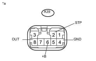
Measure the voltage according to the value(s) in the table below.
Standard Voltage Tester Connection Switch Condition Specified Condition A39-6 (+B) - A39-4 (GND) Always 11 to 14 V A39-2 (STP) - Body grand Brake pedal depressed 11 to 14 V Brake pedal not depressed Below 1 V A39-8 (OUT) - Body grand Brake pedal depressed 11 to 14 V Brake pedal not depressed Below 1 V If the result is not as specified, replace the stop light control relay assembly.
Table 1. Text in Illustration *a Component with harness connected
(Stop Light Control Relay Assembly
-
-
Click here
INSPECT INTEGRATION RELAY (DRL)
Table 2. Text in Illustration *A for LHD *B for RHD *a Component without harness connected
(Integration Relay)
- - Note:
-
The DRL relay is built into the integration relay.
-
Before performing the relay inspections for the relays of the integration relay, inspect the DRL fuse.
-
Inspect the DRL relay.
-
Measure the resistance and voltage according to the value(s) in the table below.
for LHD Table 3. Standard Resistance: Tester Connection Condition Specified Condition 1Y-1 - 1R-3 Always 10 kΩ or higher Table 4. Standard Voltage: Tester Connection Condition Specified Condition 1R-3 - Body ground Battery voltage is applied to terminals 1Y-1 and 1R-4 11 to 14 V for RHD Table 5. Standard Resistance: Tester Connection Condition Specified Condition 1X-1 - 1R-3 Always 10 kΩ or higher Table 6. Standard Voltage: Tester Connection Condition Specified Condition 1R-3 - Body ground Battery voltage is applied to terminals 1X-1 and 1R-4 11 to 14 V If the result is not as specified, replace the integration relay.
-
-