HAZARD WARNING SWITCH INSPECTION
PROCEDURE
-
INSPECT HAZARD WARNING SIGNAL SWITCH ASSEMBLY (w/o Audio)
-
Inspect the hazard warning signal switch assembly.
-
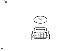
Text in Illustration *a Component without harness connected
(Hazard Warning Signal Switch Assembly)
Measure the resistance according to the value(s) in the table below.
Standard Resistance Tester Connection Switch Condition Specified Condition 4 - 1 Hazard warning switch off 10 kΩ or higher Hazard warning switch on Below 1 Ω If the result is not as specified, replace the hazard warning signal switch assembly.
-
-
Check the illumination.
-
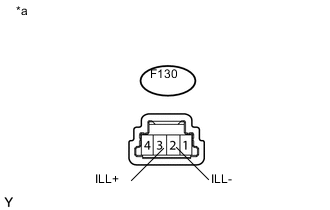
Text in Illustration *a Component without harness connected
(Hazard Warning Signal Switch Assembly)
Apply battery voltage to the connector, and check the LED illumination condition.
OK Measurement Condition Specified Condition Battery positive (+) → F130-3 (ILL+)
Battery negative (-) → F130-2 (ILL-)
Illuminates If the result is not as specified, replace the hazard warning signal switch assembly.
-
-
-
INSPECT CLOCK ASSEMBLY (for Radio and Display Type)
-
Inspect the clock assembly.
-
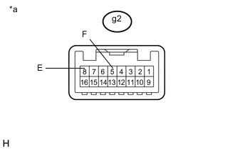
Text in Illustration *a Component without harness connected
(Clock Assembly)
Measure the resistance according to the value(s) in the table below.
Standard Resistance Tester Connection Switch Condition Specified Condition g2-5 (F) - g2-8 (E) Hazard warning switch off 10 kΩ or higher Hazard warning switch on Below 1 Ω If the result is not as specified, replace the clock assembly.
-
-
Check the illumination.
-
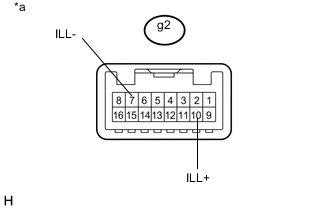
Text in Illustration *a Component without harness connected
(Clock Assembly)
Apply battery voltage to the connector, and check the LED illumination condition.
OK Measurement Condition Specified Condition Battery positive (+) → g2-10 (ILL+)
Battery negative (-) → g2-7 (ILL-)
Illuminates If the result is not as specified, replace the clock assembly.
-
-
-
INSPECT MULTI-DISPLAY ASSEMBLY (w/ Navigation System)
-
Inspect the multi-display assembly (hazard warning switch).
-
Measure the resistance according to the value(s) in the table below.
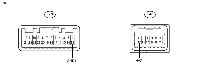
Text in Illustration *a Component without harness connected
(Multi-display Assembly)
- - Standard Resistance Tester Connection Switch Condition Specified Condition F97-12 (HAZ) - F79-13 (GND1) Hazard warning switch off 10 kΩ or higher Hazard warning switch on Below 1 Ω If the result is not as specified, replace the multi-display assembly.
-
-
Check the illumination.
-
Apply battery voltage to the connector and check the LED illumination conditions.
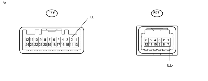
Text in Illustration *a Component without harness connected
(Multi-display Assembly)
- - OK Measurement Condition Specified Condition Battery positive (+) → F79-2 (ILL)
Battery negative (-) → F97-7 (ILL-)
Illuminates If the result is not as specified, replace the multi-display assembly.
-
-