HAZARD WARNING SWITCH INSPECTION
PROCEDURE
-
INSPECT HAZARD WARNING SIGNAL SWITCH ASSEMBLY
-
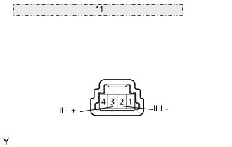
*1 Component without harness connected: (Hazard Warning Switch) Inspect the hazard warning switch LED illumination.
-
Apply battery voltage to the connector, and check the LED illumination condition.
OK Measurement Condition Specified Condition Battery positive (+) → Terminal 3 (ILL+)
Battery negative (-) → Terminal 2 (ILL-)
Light illuminates -
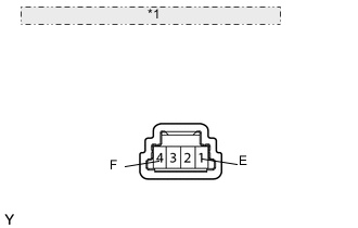
*1 Component without harness connected: (Hazard Warning Switch) Measure the resistance according to the value(s) in the table below.
Standard Resistance Tester Connection Switch Condition Specified Condition 4 (F) - 1 (E) Hazard warning signal switch off 10 kΩ or higher 4 (F) - 1 (E) Hazard warning signal switch on Below 1 Ω If the result is not as specified, there may be a malfunction in the hazard warning switch.
-
-