LIGHTING SYSTEM Headlight Beam Level Control Actuator Circuit
DESCRIPTION
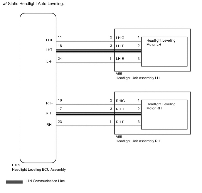
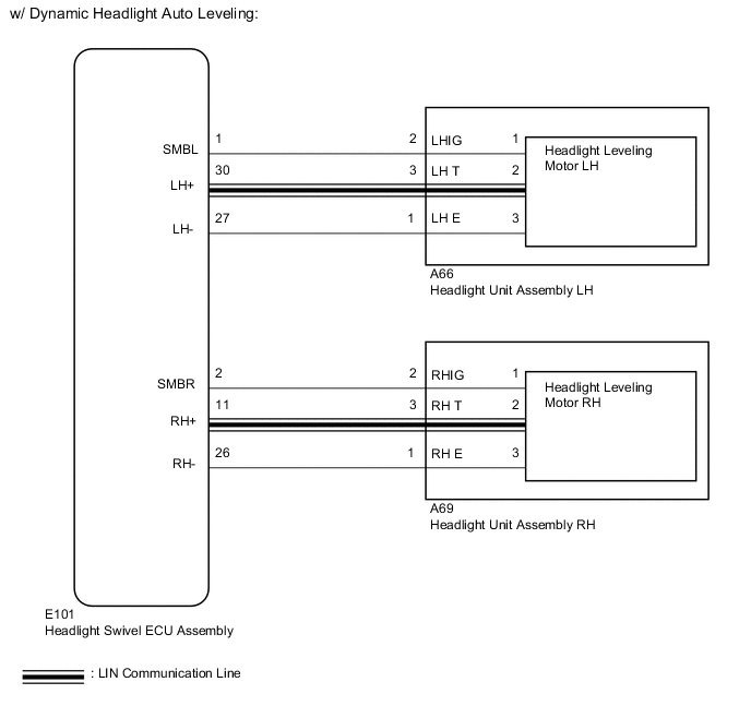
The headlight leveling ECU*1 or headlight swivel ECU*2 actuates the headlight leveling motors according to the vehicle conditions.
-
*1: w/ Static Headlight Auto Leveling
-
*2: w/ Dynamic Headlight Auto Leveling
WIRING DIAGRAM
CAUTION / NOTICE / HINT
Note
After replacing the headlight leveling ECU*1 or headlight swivel ECU*2, initialization of the ECU is necessary Click here.
-
*1: w/ Static Headlight Auto Leveling
-
*2: w/ Dynamic Headlight Auto Leveling
PROCEDURE
-
PERFORM ACTIVE TEST USING GTS (HEADLIGHT LEVELING MOTOR)
-
Using the GTS, perform the Active Test Click here.
HL Auto Leveling (w/ Static Headlight Auto Leveling) Tester Display Test Part Control Range Diagnostic Note HL Auto Leveling This test activates the Leveling Motor of the LH and RH headlights. By activating the Leveling Motor, illumination direction of the headlights can be moved up/down. Up, Down, Stop Perform the Active Test with the vehicle stopped, the ignition switch ON and the low beam headlights on. AFS (w/ Dynamic Headlight Auto Leveling) Tester Display Test Part Control Range Diagnostic Note HL Auto Leveling This test activates the Leveling Motor of the LH and RH headlights. By activating the Leveling Motor, illumination direction of the headlights can be moved up/down. Up, Down, Stop Perform the Active Test with the vehicle stopped, the ignition switch ON and the low beam headlights on.
-
*: Perform the Active Test with the engine running and vehicle stopped.
OK Headlight leveling motors operate normally. -
OK 
PROCEED TO NEXT SUSPECTED AREA SHOWN IN PROBLEM SYMPTOMS TABLE Click here
NG 
-
-
CHECK VEHICLE TYPE
-
Check the vehicle type.
Result Result Proceed to w/ Static Headlight Auto Leveling A w/ Dynamic Headlight Auto Leveling B
B 
CHECK HARNESS AND CONNECTOR (HEADLIGHT UNIT ASSEMBLY - HEADLIGHT SWIVEL ECU ASSEMBLY) Click here
A
-
-
CHECK HARNESS AND CONNECTOR (HEADLIGHT UNIT ASSEMBLY - HEADLIGHT LEVELING ECU ASSEMBLY)
-
Disconnect the E109 headlight leveling ECU connector.
-
Disconnect the A66*1 or A69*2 headlight leveling motor connector.
-
*1: for LH
-
*2: for RH
-
-
Measure the resistance according to the value(s) in the table below.
Standard Resistance for LH Tester Connection Condition Specified Condition E109-11 (LH+) - A66-2 (LHIG) Always Below 1 Ω E109-18 (LHT) - A66-3 (LH T) Always Below 1 Ω E109-24 (LH-) - A66-1 (LH E) Always Below 1 Ω E109-11 (LH+) - Body ground Always 10 kΩ or higher E109-18 (LHT) - Body ground Always 10 kΩ or higher E109-24 (LH-) - Body ground Always 10 kΩ or higher for RH Tester Connection Condition Specified Condition E109-10 (RH+) - A69-2 (RHIG) Always Below 1 Ω E109-17 (RHT) - A69-3 (RH T) Always Below 1 Ω E109-23 (RH-) - A69-1 (RH E) Always Below 1 Ω E109-10 (RH+) - Body ground Always 10 kΩ or higher E109-17 (RHT) - Body ground Always 10 kΩ or higher E109-23 (RH-) - Body ground Always 10 kΩ or higher
OK
INSPECT HEADLIGHT UNIT ASSEMBLY Click here
NG
REPAIR OR REPLACE HARNESS OR CONNECTOR
-
-
CHECK HARNESS AND CONNECTOR (HEADLIGHT UNIT ASSEMBLY - HEADLIGHT SWIVEL ECU ASSEMBLY)
-
Disconnect the E101 headlight swivel ECU connector.
-
Disconnect the A66*1 or A69*2 headlight leveling motor connector.
-
*1: for LH
-
*2: for RH
-
-
Measure the resistance according to the value(s) in the table below.
Standard Resistance for LH Tester Connection Condition Specified Condition E101-1 (SMBL) - A66-2 (LHIG) Always Below 1 Ω E101-30 (LH+) - A66-3 (LH T) Always Below 1 Ω E101-27 (LH-) - A66-1 (LH E) Always Below 1 Ω E101-1 (SMBL) - Body ground Always 10 kΩ or higher E101-30 (LH+) - Body ground Always 10 kΩ or higher E101-27 (LH-) - Body ground Always 10 kΩ or higher for RH Tester Connection Condition Specified Condition E101-2 (SMBR) - A69-2 (RHIG) Always Below 1 Ω E101-11 (RH+) - A69-3 (RH T) Always Below 1 Ω E101-26 (RH-) - A69-1 (RH E) Always Below 1 Ω E101-2 (SMBR) - Body ground Always 10 kΩ or higher E101-11 (RH+) - Body ground Always 10 kΩ or higher E101-23 (RH-) - Body ground Always 10 kΩ or higher
NG
REPAIR OR REPLACE HARNESS OR CONNECTOR
OK
-
-
INSPECT HEADLIGHT UNIT ASSEMBLY
-
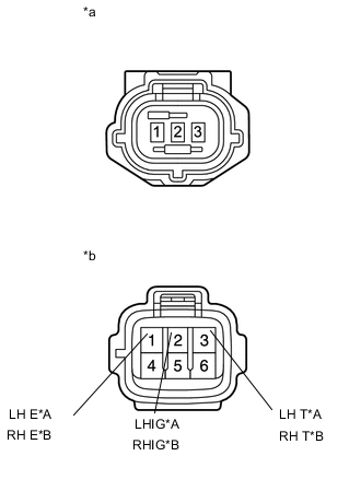
Text in Illustration *A for LH *B for RH *a Front view of wire harness connector
(to Headlight Leveling Motor)
*b Component without harness connected
(Headlight Unit Assembly)
Remove the headlight unit.
for LED Headlight Click here.
for Halogen Headlight and LED Headlight Click here.
-
Disconnect the headlight leveling motor connector.
-
Measure the resistance according to the value(s) in the table below.
Standard Resistance for LH Tester Connection Condition Specified Condition 2 (LHIG) - 1 Always Below 1 Ω 3 (LH T) - 2 1 (LH E) - 3 for RH Tester Connection Condition Specified Condition 2 (RHIG) - 1 Always Below 1 Ω 3 (RH T) - 2 1 (RH E) - 3 Result Result Proceed to OK A NG (for LED Headlight) B NG (for Halogen Headlight and LED Headlight) C
B
REPLACE HEADLIGHT UNIT ASSEMBLY Click here
C
REPLACE HEADLIGHT UNIT ASSEMBLY Click here
A
-
-
CHECK HEADLIGHT LEVELING MOTOR
-
Temporarily replace the headlight leveling motor with a new or normally functioning one Click here.
-
Perform the Active Test of the leveling motors Click here.
OK Headlight leveling motors operate normally. Result Result Proceed to OK A NG (w/ Static Headlight Auto Leveling) B NG (w/ Dynamic Headlight Auto Leveling) (for LHD) C NG (w/ Dynamic Headlight Auto Leveling) (for RHD) D
A
END (HEADLIGHT LEVELING MOTOR WAS DEFECTIVE)
B
REPLACE HEADLIGHT LEVELING ECU ASSEMBLY Click here
C
REPLACE HEADLIGHT SWIVEL ECU ASSEMBLY Click here
D
REPLACE HEADLIGHT SWIVEL ECU ASSEMBLY Click here
-