LIGHTING SYSTEM Headlight Leveling ECU Power Source Circuit
DESCRIPTION
This circuit detects the state of the ignition switch, and sends it to the headlight leveling ECU*1 or headlight swivel ECU*2.
-
*1: w/ Static Headlight Auto Leveling
-
*2: w/ Dynamic Headlight Auto Leveling
WIRING DIAGRAM
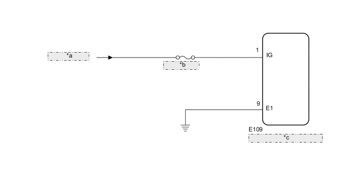
| *a | from IG1 Relay |
| *b | ENG-IG NO. 1 |
| *c | Headlight Leveling ECU Assembly |
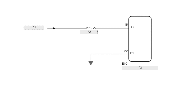
| *1 | from IG1 Relay |
| *2 | ENG-IG NO. 1 |
| *3 | Headlight Swivel ECU Assembly |
CAUTION / NOTICE / HINT
Note
-
Inspect the fuses for circuits related to this system before performing the following inspection procedure.
-
After replacing the headlight leveling ECU*1 or headlight swivel ECU*2, initialization of the ECU is necessary Click here.
-
*1: w/ Static Headlight Auto Leveling
-
*2: w/ Dynamic Headlight Auto Leveling
PROCEDURE
-
CHECK VEHICLE TYPE
-
Check the vehicle type.
Result Result Proceed to w/ Static Headlight Auto Leveling A w/ Dynamic Headlight Auto Leveling B
B 
READ VALUE USING GTS (IGNITION POWER SUPPLY) Click here
A 
-
-
READ VALUE USING GTS (IGNITION POWER SUPPLY)
-
Using the GTS, read the Data List Click here.
HL Auto Leveling Tester Display Measurement Item/Range Normal Condition Diagnostic Note +B Ignition power supply voltage value / 0 to 19.75 V 11 to 14 V - OK The display is as specified in the normal condition column.
OK 
PROCEED TO NEXT SUSPECTED AREA SHOWN IN PROBLEM SYMPTOMS TABLE Click here
NG
-
-
CHECK HARNESS AND CONNECTOR (HEADLIGHT LEVELING ECU ASSEMBLY - BATTERY AND BODY GROUND)
-
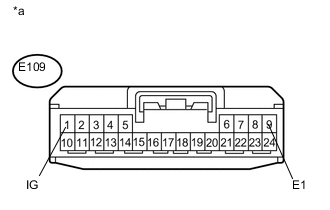
Text in Illustration *a Front view of wire harness connector
(to Headlight Leveling ECU Assembly)
Disconnect the headlight leveling ECU connector.
-
Measure the voltage according to the value(s) in the table below.
Standard Voltage Tester Connection Switch Condition Specified Condition E109-1 (IG) - Body ground Ignition switch ON 11 to 14 V Ignition switch off Below 1 V -
Measure the resistance according to the value(s) in the table below.
Standard Resistance Tester Connection Condition Specified Condition E109-9 (E1) - Body ground Always Below 1 Ω
OK
REPLACE HEADLIGHT LEVELING ECU ASSEMBLY Click here
NG
REPAIR OR REPLACE HARNESS OR CONNECTOR
-
-
READ VALUE USING GTS (IGNITION POWER SUPPLY)
-
Using the GTS, read the Data List Click here.
AFS Tester Display Measurement Item/Range Normal Condition Diagnostic Note +B Ignition power supply voltage value / 0 to 19.75 V 11 to 14 V - OK The display is as specified in the normal condition column.
OK
PROCEED TO NEXT SUSPECTED AREA SHOWN IN PROBLEM SYMPTOMS TABLE Click here
NG
-
-
CHECK HARNESS AND CONNECTOR (HEADLIGHT SWIVEL ECU ASSEMBLY - BATTERY AND BODY GROUND)
-
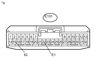
Text in Illustration *a Front view of wire harness connector
(to Headlight Swivel ECU Assembly)
Disconnect the headlight swivel ECU connector.
-
Measure the voltage according to the value(s) in the table below.
Standard Voltage Tester Connection Switch Condition Specified Condition E101-15 (IG) - Body ground Ignition switch ON 11 to 14 V Ignition switch off Below 1 V -
Measure the resistance according to the value(s) in the table below.
Standard Resistance Tester Connection Condition Specified Condition E101-22 (E1) - Body ground Always Below 1 Ω Result Result Proceed to OK (for LHD) A OK (for RHD) B NG C
A
REPLACE HEADLIGHT SWIVEL ECU ASSEMBLY Click here
B
REPLACE HEADLIGHT SWIVEL ECU ASSEMBLY Click here
C
REPAIR OR REPLACE HARNESS OR CONNECTOR
-